In the atmosphere absorption occurs and energy is lost in heating the air molecules. Absorption caused by this is minimal at frequencies below about 10 GHz but absorption by foliage, particularly when wet, is severe at VHF and above.
Waves travelling along the earth’s surface create currents in the earth causing ground absorption which increases with frequency. A horizontally polarized surface wave suffers more ground absorption than a vertically polarized wave because of the ‘short-circuiting’ by the ground of the electric field. Attenuation at a given frequency is least for propagation over water and greatest over dry ground for a vertically polarized wave.
As radio waves travel more slowly in dense media and the densest part of the atmosphere is normally the lowest, the upper parts of a wave usually travel faster than the lower. This refraction (Figure 1.7)has the effect of bending the wave to follow the curvature of the earth and progressively tilting the wavefront until eventually the wave becomes horizontally polarized and short-circuited by the earth’s conductivity.
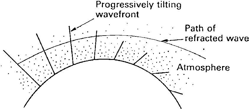 Figure 1.7 Effects of refraction
Waves travelling above the earth’s surface (space waves) are usually refracted downwards, effectively increasing the radio horizon to greater than the visual.
The refractive index of the atmosphere is referred to as the K factor; a K factor of 1 indicates zero refraction. Most of the time K is positive at 1.33 and the wave is bent to follow the earth’s curvature. The radio horizon is then 4/3 times the visual. However, the density of the atmosphere varies from time to time and in different parts of the world. Density inversions where higher density air is above a region of low density may also occur. Under these conditions the K factor is negative and radio waves are bent away from the earth’s surface and are either lost or ducting occurs. A K factor of 0.7 is the worst expected case.
Ducting occurs when a wave becomes trapped between layers of differing density only to be returned at a great distance from its source, possibly creating interference.
The radio horizon at VHF/UHF and up is approximately 15% further than the optical horizon. Several equations are used in calculating the distance. If D− is the distance to the radio horizon, and H is the antenna height, then:
D√H = kWhen D is in statute miles (5280 feet) and H in feet, then k = 1.42.•
• When D is in nautical miles (6000 feet) and H in feet, then k = 1.23.
• When D is in kilometres and H is in metres, then k = 4.12. Repeating the calculation for the receiving station and adding the results gives the total path length.
When a wave passes over on the edge of an obstacle some of its energy is bent in the direction of the obstacle to provide a signal in what would otherwise be a shadow. The bending is most severe when the wave passes over a sharp edge (Figure 1.8).
b′′′Ray b b′′
a′′b′
Ray a a′b a′
Shadowa
Subsequent wavefront
As with light waves, the subsequent wavefront consists of wavelets produced from an infinite number of points on the wavefront, rays a and b in Figure 1.8 (Huygens’ principle). This produces a pattern of interfering waves of alternate addition and subtraction.
Radio waves are reflected from surfaces lying in and along their path and also, effectively, from ionized layers in the ionosphere – although most of the reflections from the ionized layers are actually the products of refraction. The strength of truly reflected signals increases with frequency, and the conductivity and smoothness of the reflecting surface.
Reflection, refraction and diffraction may provide signals in what would otherwise be areas of no signal, but they also produce interference.
Reflected – or diffracted – signals may arrive at the receiver in any phase relationship with the direct ray and with each other. The relative phasing of the signals depends on the differing lengths of their paths and the nature of the reflection.
When the direct and reflected rays have followed paths differing by an odd number of half-wavelengths they could be expected to arrive at the receiver in anti-phase with a cancelling effect. However, in the reflection process a further phase change normally takes place. If the reflecting surface had infinite conductivity, no losses would occur in the reflection, and the reflected wave would have exactly the same or opposite phase as the incident wave depending on the polarization in relation to the reflecting surface. In practice, the reflected wave is of smaller amplitude than the incident, and the phase relationships are also changed. The factors affecting the phasing are complex but most frequently, in practical situations, approximately 180æ phase change occurs on reflection, so that reflected waves travelling an odd number of half-wavelengths arrive in phase with the direct wave while those travelling an even number arrive anti-phase.
As conditions in the path between transmitter and receiver change so does the strength and path length of reflected signals. This means that a receiver may be subjected to signal variations of almost twice the mean level and practically zero, giving rise to severe fading. This type of fading is frequency selective and occurs on troposcatter systems and in the mobile environment where it is more severe at higher frequencies. A mobile receiver travelling through an urban area can receive rapid signal fluctuations caused by additions and cancellations of the direct and reflected signals at half-wavelength intervals. Fading due to the multi-path environment is often referred to as Rayleigh fading and its effect is shown in Figure 1.9. Rayleigh fading, which can cause short signal dropouts, imposes severe restraints on mobile data transmission.
100 Average signal levelThe quality of radio signals is not only degraded by the propagation losses: natural or manmade electrical noise is added to them, reducing their intelligibility.
Atmospheric noise includes static from thunderstorms which, unless very close, affects frequencies below about 30 MHz and noise from space is apparent at frequencies between about 8 MHz to 1.5 GHz.
A type of noise with which radio engineers are continually concerned is thermal. Every resistor produces noise spread across the whole frequency spectrum. Its magnitude depends upon the ohmic value of the resistor, its temperature and the bandwidth of the following circuits. The noise voltage produced by a resistor is given by:
E = √4kTBRnwhere
En = noise voltage, V(RMS)
k = Boltzmann’s constant
= 1.38× 10⁻²³ joules/kelvin
T = temperature in degrees K
B = bandwidth of measurement, Hz
R = resistance in ohms
Noise is produced in every electronic component. Shot noise – it sounds like falling lead shot – caused by the random arrival of electrons at, say, the collector of a transistor, and the random division of electrons at junctions in devices, add to this noise.
Doppler effect is an apparent shift of the transmitted frequency which occurs when either the receiver or transmitter is moving. It becomes significant in mobile radio applications towards the higher end of the UHF band and on digitally modulated systems.
When a mobile receiver travels directly towards the transmitter each successive cycle of the wave has less distance to travel before reaching the receiving antenna and, effectively, the received frequency is raised. If the mobile travels away from the transmitter, each successive cycle has a greater distance to travel and the frequency is lowered. The variation in frequency depends on the frequency of the wave, its propagation velocity and the velocity of the vehicle containing the receiver. In the situation where the velocity of the vehicle is small compared with the velocity of light, the frequency shift when moving directly towards, or away from, the transmitter is given to sufficient accuracy for most purposes by:
Vfd = Cft
where
fd = frequency shift, Hz
ft = transmitted frequency, Hz V = velocity of vehicle, m/s C = velocity of light, m/s
• 100 km/hr at 450 MHz, frequency shift = 41.6Hz
• 100 km/hr at 1.8 GHz – personal communication network (PCN) frequencies – frequency shift = 166.5Hz
• Train at 250 km/hr at 900 MHz – a requirement for the GSM panEuropean radio-telephone – frequency shift = 208 Hz
When the vehicle is travelling at an angle to the transmitter the frequency shift is reduced. It is calculated as above and the result multiplied by the cosine of the angle of travel from the direct approach (Figure 1.10).
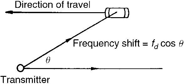 Figure 1.10 Doppler frequency shift and angle to transmitter
In a radar situation Doppler effect occurs on the path to the target and also to the reflected signal so that the above formula is modified to:
2V
fd = C ft
where fd is now the total frequency shift.