The effects of all of the above phenomena vary with frequency and are used in the selection of frequencies for specific purposes. The behaviour of waves of different frequencies gives rise to the principal types of wave propagation.
Waves in the bands from very low frequencies (VLF, 3–30 kHz), low frequencies (LF, 30–300 kHz) and medium frequencies (MF, 300–3000 kHz) travel close to the earth’s surface: the ground wave (Figure 1.11). Transmissions using the ground wave must be vertically polarized to avoid the conductivity of the earth short-circuiting the electric field.
Direct ray Space wave Reflected rayThe ground wave consists of a surface wave and a space wave. The surface wave travels along the earth’s surface, and is attenuated by ground absorption and the tilting of the wavefront due to diffraction. The losses increase with frequency and thus VLF radio stations have a greater range than MF stations. The attenuation is partially offset by the replacement of energy from the upper part of the wave refracted by the atmosphere.
The calculation of the field strength of the surface wave at a distance from a transmitter is complex and affected by several variables. Under plane earth conditions and when the distance is sufficiently short that the earth’s curvature can be neglected the field intensity is given by:
E 2E0Asu = dwhere
Esu = field intensity in same units as E0
d = distance in same units of distance as used in E0
A = a factor calculated from the earth losses, taking frequency,
E0 = the free space field produced at unit distance from the transmitter. (With a short (compared with λ/4) vertical aerial, 2E0 = 300√P mV/m at 1 km where P is the radiated power in kW.) (Terman, 1943)
For a radiated power of 1 kW and ground of average dampness, the distance at which a field of 1 mV/m will exist is given in Table 1.2.Table 1.2 Distance at which a field of 1 mV/m will exist for a radiated power of 1 kW and ground of average dampness
Frequency Range (km)100 kHz 200
1MHz 60
10 MHz 6
100 MHz 1.5
The direct and reflected components of the ground wave produce multi-path propagation and variations in received single strength will arise depending on the different path lengths taken by the two components. When the transmitting and receiving antennas are at ground level the components of the space wave cancel each other and the surface wave is dominant. When the antennas are elevated, the space wave becomes increasingly strong and a height is eventually reached where the surface wave has a negligible effect on the received signal strength.
High frequency (HF) waves between 3 MHz and 30 MHz are effectively reflected by ionized layers in the ionosphere producing the sky wave. Medium frequency waves may also be reflected, but less reliably.
The ionosphere contains several layers of ionized air at varying altitudes (Figure 1.12). The heights and density of the layers vary diurnally, seasonally and with the incidence of sunspot activity. The Eand F2 layers are semi-permanent while the F1 layer is normally only present during daytime.
Radio waves radiated at a high angle and reflected by these layers return to earth at a distance from the transmitter. The HF reflection process is in reality one of refraction in layers possessing a greater free electron density than at heights above or below them. The speed of propagation is slowed on entering a layer and the wave is bent and, if of a suitable frequency and angle of incidence, returned to earth (Figure 1.13). The terms used are defined as follows:
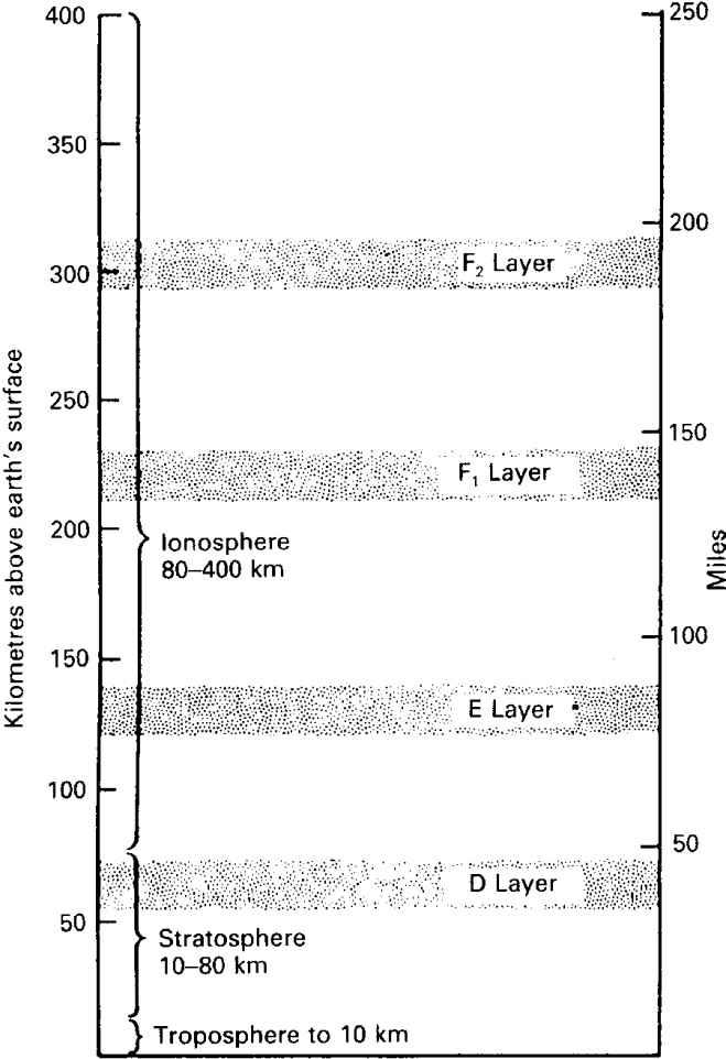 Figure 1.12 The ionosphere
Virtual height . The height at which a true reflection of the incident•
wave would have occurred (Figure 1.13).
• Critical frequency (fc). The highest frequency that would be returned to earth in a wave directed vertically at the layer.
• Maximum usable frequency (muf). The highest frequency that will be returned to earth for a given angle of incidence. If the angle of incidence to the normal is θ, the muf = fc/cosθ.
• Skip distance. The minimum distance from the transmitter, along the surface of the earth, at which a wave above the critical frequency will be returned to earth (Figure 1.12). Depending on the frequency, the ground wave will exist at a short distance from the transmitter.
• Sporadic E-layer reflections. Reflections from the E layer at frequencies higher than those which would normally be returned to earth. They appear to be reflections from electron clouds having sharp boundaries and drifting through the layer. As the name implies the reflections are irregular but occur mostly in summer and at night.
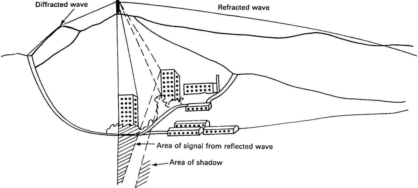 Figure 1.14 Pictorial representation of radio coverage from a base station
both direct and reflected components (see Figure 1.11), and is affected by refraction and diffraction. The importance of these effects varies with frequency, the nature of the terrain and of objects close to the direct path, and the type of communication, e.g. data. Apart from medium-wave broadcasting, space waves are used mainly for communications using frequencies of VHF and upwards.
The range of space waves is the radio horizon. However, places of little or no signal can arise in the lee of radio obstacles. Fortunately, they may be filled with either reflected or diffracted signals as depicted in Figure 1.14.
The tropospheric, or forward, scatter effect provides reliable, over the horizon, communication between fixed points at bands of ultra and super high frequencies. Usable bands are around 900, 2000 and 5000 MHz and path lengths of 300 to 500 km are typical.
The mechanism is not known with certainty but reflections from discontinuities in the dielectric constant of the atmosphere and scattering of the wave by clouds of particles are possibilities. It is an inefficient process, the scattered power being −60 to −90 dB relative to the incident power, so high transmitter powers are necessary. The phenomenon is regularly present but is subject to two types of fading. One occurs slowly and is due to variations of atmospheric conditions. The other is a form of Rayleigh fading and is rapid, deep and frequency selective. It is due to the scattering occurring at different points over a volume in the atmosphere producing multipath propagation conditions.
Troposcatter technique uses directional transmitting and receiving antennas aimed so that their beams intercept in the troposphere at the mid-distance point. To overcome the fading, diversity reception using multiple antennas spaced over 30 wavelengths apart is common.