* ------------------------------------------------------–
GLOBAL
ZMESH
%1 -3.5 0.2
-3.5 3.5 0.1
3.5 %2 0.2
END RMESH
0.0 4.5 0.1
4.5 %3 0.2
END END
* ------------------------------------------------------–
REGION FILL AIR
L %1 0.00000 %2 0.00000
L %2 0.00000 %2 %3
L %2 %3 %1 %3
L %1 %3 %1 0.00000
END
* ------------------------------------------------------–
REGION FILL COIL
L -3.00000 2.00000 3.00000 2.00000
L 3.00000 2.00000 3.00000 4.00000
L 3.00000 4.00000 -3.00000 4.00000
L -3.00000 4.00000 -3.00000 2.00000
END
* ------------------------------------------------------–
REGION BOUNDARY
L %1 0.00000 %2 0.00000
L %2 0.00000 %2 %3
L %2 %3 %1 %3
L %1 %3 %1 0.00000
END
* ------------------------------------------------------–
ENDFILE
Note the symbolic representation of the boundary limits, a convention familiar to users of Windows batch files. The symbol %1 represents zmin, %2 represents zmax and %3 represents rmax.
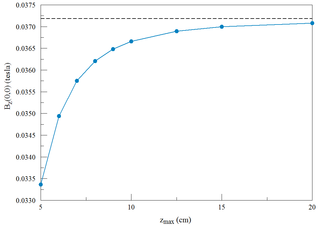
Figure 32: Results of the solution set. Dashed line shows the theoretical free-space value.
We prepare a Windows batch file with the following content:
START /B /WAIT C:fieldp_protricompmesh.exe C:BatchControl – 5.00 5.00 7.50
START /B /WAIT C:fieldp_protricomppermag.exe C:BatchControl.PIN
START /B /WAIT C:fieldp_protricomppermag.exe C:BatchControl.SCR
START /B /WAIT C:fieldp_protricompmesh.exe C:BatchControl – 6.00 6.00 9.00
START /B /WAIT C:fieldp_protricomppermag.exe C:BatchControl.PIN
START /B /WAIT C:fieldp_protricomppermag.exe C:BatchControl.SCR
START /B /WAIT C:fieldp_protricompmesh.exe C:BatchControl – 7.00 7.00 10.50
START /B /WAIT C:fieldp_protricomppermag.exe C:BatchControl.PIN
START /B /WAIT C:fieldp_protricomppermag.exe C:BatchControl.SCR
START /B /WAIT C:fieldp_protricompmesh.exe C:BatchControl – 8.00 8.00 12.00
START /B /WAIT C:fieldp_protricomppermag.exe C:BatchControl.PIN
START /B /WAIT C:fieldp_protricomppermag.exe C:BatchControl.SCR
...
The file seems verbose, but it is mainly copy-and-paste from a template prepared with the Create task button of the TriComp program launcher. The interesting lines are those that call Mesh. The first pass parameter is the prefix of the input script listed above. The three additional string parameters give numerical values for the variables %1, %2 and %3. There are multiple solutions with expanding boundaries with the constraint rmax = 1.5zmax. The two commands that follow run PerMag with the modified mesh and then execute the analysis script BatchControl.SCR. This file has the following content:
INPUT BatchControl.POU
OUTPUT BatchControl.DAT Append
POINT 0.0 0.0
ENDFILE
The Append specification in the second command ensures that all the data will be added in sequence to a single output file.
The full data set is generated in about two seconds by executing the batch file. The data are available as text entries in BatchControl.DAT. Figure 32 shows a plot of the results. The dashed line is the theoretical result from Eq. 5. The difference from the infinite-space result is about 10.4% for the close boundaries (zmax = 5.0 cm) and about 0.4% for the large boundaries (zmax = 20.0 cm). The next chapter discusses the role of steel in magnet design. In particular, we will improve the example solenoid, providing external shielding and minimizing the drive power to achieve a given internal field.