56555-287-3, New Orleans, January 2005, SCS.
Norman S. Nise, (2000). Control Systems Engineering, John Wiley & Sons, ISBN:970-24-0254-9,
United States of America.
Peter Gawthrop, Lorcan Smith (1996)., Metamodelling, Prentice-Hall,ISBN:0-13-489824-9,
Great Britain.
P.E. Wellstead, (1979). Physical System Modelling, Academic Press, ISBN:0-12-744380-0
London.
P. J. Gawthrop and D. Palmer, (2003). A bicausal bond graph representation of operational
amplifiers", Proceedings of the Institution of Mechanical Engineers Part I: Journal
Systems and Control Engineering, Vol. 217
Ramakant A. Gayakward, (2000), Op-amps and Linear Integrated Circuit, Prentice Hall,
ISBN:0-13-280868-4, United States of America.
314
New Approaches in Automation and Robotics
Thomas L. Floyd and David Buchla, (1999), Basic Operational Amplifiers and Linear Integrated
Circuits, Prentice-Hall, ISBN:0-13-082987-0, United States of America.
William D. Stanley, (1994). Operational Amplifiers with Linear Integrated Circuits, Maxwell
Macmillan International
20-Sim, Controllab Products (2007) B. V., 20-Sim, http://www.20sim.com/ product/20sim.html
17
Hypermobile Robots
Grzegorz Granosik
Technical University of Lodz
Poland
1. Introduction
Hypermobile robots belong to the group of hyper-redundant articulated mobile robots. This
group can be further divided based on two characteristic features: the way the forward
motion of the robot is generated and the activity of its joints, as shown in Table 1.
Propulsion→
External propulsion elements:
Movement is generated by
Joints↓
legs, wheels, tracks
undulation
Hypermobile robots:
• Koryu-I and Koryu-II (Hirose, 1993)
• Snake 2 (Klaassen and Paap, 1999)
Snake-like robots:
• Soryu (Takayama and Hirose, 2000)
• Active Cord Mechanism whole
• Millibot Train (Brown et al., 2002)
family of robots (Hirose, 1993)
• Moira (Osuka & Kitajima, 2003)
• Slim Slime Robot (Ohno &
Active joints • Pipeline Explorer (Schempf et al., 2003) Hirose, 2000)
• Omnis family (Granosik et al., 2005)
• Snake robots by Dr. Gavin
• MAKRO plus (Streich & Adria, 2004)
Miller (snakerobots.com)
• KOHGA (Kamegawa et al., 2004)
• Perambulator-II (Ye et al., 2007)
• JL-I (Zhang et al., 2006)
• Wheeeler (Pytasz & Granosik, 2006)
Active wheels – passive joints robots:
Passive joints •
Genbu 3 ( Kimura & Hirose, 2002)
Table 1. Articulated mobile robots
Articulated robots can also be divided in other way, as suggested by Robinson and Davies
(1999), into three groups: discrete, serpentine and continuum. Most robots are discrete
mechanisms constructed from series of rigid links interconnected by discrete joints. In case
of robotic manipulators joints are usually one degree of freedom (DOF) but in case of
articulated mobile robots we can find 2 and 3 DOF joints more often. Multi degree of
freedom joints create naturally spatial devices, which can bend in any direction.
Serpentine robots also utilize discrete joints but combine very short rigid links with a large
density of joints. This creates highly mobile mechanisms producing smooth curves, similar
to snake. And therefore representatives of this group of robots are also called snake-like
316
New Approaches in Automation and Robotics
robots, as shown in Fig. 1. Some of the hypermobile robots feature very short links relative
to the cross section size and also belong to this group.
Fig. 1. Active Cord Mechanism (left) reproduced from (Hirose, 1993), ACM-R3 reproduced
from (Mori & Hirose, 2002)
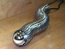
Continuum robots do not contain rigid links and identifiable rotational joints. Instead the
structures bend continuously along their length via elastic deformation and produce motion
through the generation of smooth curves, similar to the tentacles. The good example of
continuum mobile robots is Slim Slime Robot (see Fig. 2).
Fig. 2. Slim Slime Robot reproduced from (Ohno & Hirose, 2000)
In the next part of this paper we present a few major projects of hypermobile robots from
around the world, focusing on comparison of design concepts, main features, performance,
teleoperation or automated operation techniques. Finally, we present our own hypermobile
robot Wheeeler showing design concept, model, simulation results, construction and tests of
prototype. In conclusion we summarize this digest with a table showing basic properties of
presented robots. We also show advantages and disadvantages of our design and future
plans. We hope to show some general ideas on designing, constructing and control of such
complex devices as hypermobile robots with many redundant degrees of freedom.
2. History of hypermobile robots
One of the scenarios where hypermobile robots could play the main role is search and
rescue. The intensified work in this field was related to the large catastrophes happened in
different countries: Kobe earthquake, terrorist attacks on World Trade Center in New York
and bomb attacks on trains in London and Madrid. In this application robots are intended
to slither into the debris and gather visual information about possible victims. Therefore, it
is expected that robot fits small openings, can travel in the rummage of structured
Hypermobile Robots
317
environment and overcome obstacles. The other important application for hypermobile
robots are inspection tasks in sewage systems, gas pipes or venting systems.
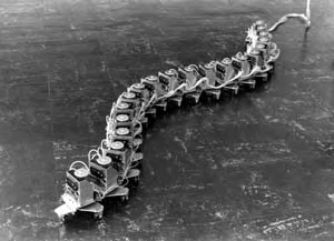
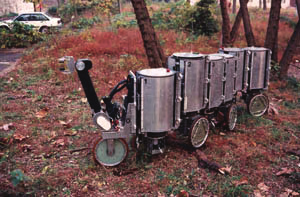
The first practical realization of a hypermobile robot, called Koryu or KR-I, was introduced
by Hirose and Morishima (1990) and later improved with version KR-II (Hirose et al., 1991),
as shown in Fig. 3. KR-II was developed with premise that it will be applied as a mobile
robot for atomic reactor. It was also considered to be used as a substitution of fireman in
rescuing activity: patrolling, gas detection, inspection and to rescue a person. This first
hypermobile robot was large and heavy, weighing in at 350 kg. The robot comprised of
multiple vertical cylindrical segments on powered wheels (tracks in KR-I) that gave the
mechanism a train-like appearance. Vertical joint actuators allow a segment to lift its
neighbors up, in order to negotiate steps or span gaps. Each segment of KR-II is equipped
with single wheel, arranged so that the unit with wheel on the right side will come after a
unit with the wheel on the left side. This single wheel design may seem unbalanced at the
first glance but its stability is secured as the segments are linked. Especially, if the vehicle
have the zigzag configuration. Moreover, this single wheel design has other advantages:
•
as each segment is connected to the body by 2DOF joint it may be seen as having sliding
active suspension,
•
the adaptability to the steep inclination during traversing can be realized by shifting all
wheels on one side up or down in vertical direction,
•
in addition, this design doesn’t require the differential mechanism of the double wheel
structure to permit different speed rotation on curves.
Fig. 3. The Koryu-I (KR-I) robot on the left and KR-II on the right (reproduced from
http://www-robot.mes.titech.ac.jp)
These robots inherited all capabilities of earlier developed snake-like robots:
•
They can go on irregular terrain with sharp rises and falls and travel a path that winds
tightly,
•
They can cross over crevasses by holding its body length rigid to act as a bridge,
•
In marshy and sandy terrain, it can move by distributing force along its entire body
length.
Additional active crawlers or wheels mounted on each segment give further advantages:
•
High speed motion – direct propulsion is more effective then undulation,
•
High load capacity – simple driving system gives large weight of load to its own weight
ratio,
•
Good portability by its unitized structure,
•
High reliability, because it is made redundant – broken segments can be easily replaced
and special segments could be added depending on mission,
318
New Approaches in Automation and Robotics
•
Versatility of the body motion – Koryu can be used not only for “locomotion”, but also
for “manipulation” – as claim authors (Hirose & Morishima, 1993).
For motion control of the robot with several wheels touching ground the force sensors to
detect reaction force were indispensable. To solve the problem, special construction of
optical based force sensing was introduced. Such sensors were mounted in both vertical and
horizontal axes to control robot among obstacles and on uneven terrain.
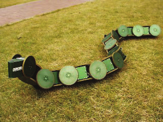
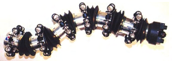
More recently, Klaassen and Paap (1999) at the German National Research Center for
Information Technology (GMD) developed the Snake2 vehicle, which contains six active
segments and a head, as shown in Fig. 4. Each round segment has an array of 12 electrically
driven wheels evenly spaced around its periphery. These wheels provide propulsion
regardless of the vehicle’s roll angle. Segments are interconnected by universal joints
actuated by three additional electric motors through strings. Snake2 is an example of a robot
that is inspired by the physiological structure of snakes where wheels replace tiny scales
observed on the bodies of some real snakes. Snake2 is equipped with six infrared distance
sensors, three torque sensors, one tilt sensor, two angle sensors in every segment, and a
video camera in the head segment. Snake2 was specifically designed for the inspection of
sewage pipes. With segments measuring 18cm in diameter and 13.5cm length Snake2
belongs to the serpentine group.
Fig. 4. Snake2 developed at the GMD
This robot was a successor of the GMD-Snake, typical continuum spatial robot built in a
very elastic way to allow flexible bending of the parts (Worst & Linnemann, 1996).
However, Authors observed an uncontrolled torsion effect which occurred when the snake
lifted some of its parts (to climb on a step). This disadvantage forced them to construct the
next generation in a more rigid way using universal joints but leaving rope-based driving
system. GMD snakes were the first articulated robots employing CAN bus communication
in the distributed control system.
Another hypermobile robot designed for sewer inspection was developed by Scholl et al.
(2000) at the Forschungszentrum Informatik (FZI) in Germany. Its segments use only two
wheels but the actuated 3-DOF joints allow full control over each segment’s spatial
orientation. The robot is able to negotiate tight 90° angled pipes and climb over 35 cm high
obstacles. One segment and its joint are about 20 cm long each. The sensor suite of this robot
is similar to that of Snake2. The development of sewer inspection robots was continued in
the joint project MAKRO plus (Streich & Adria, 2004).
MAKRO plus, is an autonomous service robot that can be used for a whole range of specific
duties within a canalization system. Robot has symmetrical construction with head
segments on both ends. These segments contain camera, structured light source and
ultrasound sensor. Four-level hierarchical control system is proposed to autonomously
Hypermobile Robots
319
drive robot inside sewage pipes. The robot’s mission is specified by human operator who
determines entry and recovery points and downloads map of all pipes and manholes in the
inspection area. Then the planning algorithm generates the sequence of actions, which are
executed by action controller. In case of obstacle detection, blockage or malfunction, planner
automatically finds new set of actions. Robot can be equipped in specialized modules. A
chemistry module measures pH levels, conductivity, O2 and temperature of waste water
with the help of a sample probe. When required, samples can be retrieved by the robot for
further analysis in a laboratory. A navigation module which can record speed and three
fiber optic gyroscopes measure the gradient and direction of the pipes in a canalization
system. This helps to support the success of the mission and it is also provides a useful and
accurate update for the land registry records, as informs INSPECTOR SYSTEMS Rainer
Hitzel GmbH.
Fig. 5. MAKRO plus robot for sewer inspection (reproduced from Streich & Adria, 2004)
While wheeled serpentine robots can work well in smooth-walled pipes, more rugged
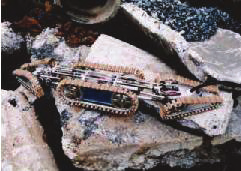
terrain requires tracked propulsion. To this effect Takayama and Hirose (2000) developed
the Souryu-I crawler, which consists of three segments, as shown in Fig. 6.
Fig. 6. Souryu from Hirose Lab (reproduced from http://www-robot.mes.titech.ac.jp)
Each segment is driven by a pair of tracks, which, in turn, are all powered simultaneously
by a single motor, located in the center segment. Torque is provided to the two distal
segments through a rotary shaft and universal joints. Each distal segment is connected to the
center segment by a special 2-DOF joint mechanism, which is actuated by two lead screws
driven by two electric motors. The robot can move forward and backward, and it can
change the orientation of the two distal segments in yaw and pitch symmetrically to the
center segment. Coordinated rotations of these joints can generate roll over motion of the
robot. One interesting feature is the ability of this robot to adapt to irregular terrain because
of the elasticity of its joints. This elasticity is provided by springs and cannot be actively
controlled. The newest incarnation – Souryu-II – is designed to separate three bodies easily
320
New Approaches in Automation and Robotics
so as to make it portable and to make it possible to add segments with special functions.
Robot is equipped with camera and batteries, and can be remotely controlled.
A different concept using unpowered joints was introduced by Kimura and Hirose (2002) at
the Tokyo Institute of Technology. That robot, called Genbu (see Fig. 7), is probably the only
serpentine robot with unpowered joints. The stability of the robot and its high mobility on
rough terrain are preserved by large-diameter wheels (220 mm). The control system
employs position and torque feedback sensors for the passive but rigid joints. Springs are
used to protect the electric motors from impact, although the stiffness of the springs cannot
be controlled during operation. Robot was intended mainly for two applications: as a fire-
fighting robot to pull a fire hose or as a planetary rover.
Fig. 7. Robot Genbu representing group of active wheels – passive joints robots
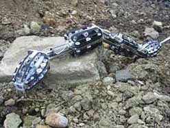
Another robot incorporating a combination of passive and active joints as well as
independently driven and coupled segments is KOHGA developed by Kamegawa et al.
(2004) and shown in Fig. 8. Robot comprises 8 segments of different structure and function:
two distal segments have CCD cameras mounted but have no propulsion means, the second
units have the right and left crawlers which are driven co-accessibly, the other segments also
have the right and left crawlers but independently driven. There is also a variety of joints
implemented in this design:
•
Two 2DOF joints driven by simple RC servos to control position of heads with cameras,
•
Two 2DOF joints with powerful DC motors and linkages to rise two segments on either
end, this improves the capability of climbing over obstacles,
•
Three 3DOF passive joints interconnecting main driving units, their function is to adjust
robot’s shape to the environment and efficiently transmit crawler force, they are passive
for light weight and simplicity.
Fig. 8. Robot KOHGA and KOHGA 2 (in a few configurations) from Matsuno Lab. at the
University of Electro-Communications
Hypermobile Robots
321
This robot implements a smart design feature: besides a camera in the front segment, there
is a second camera in the tail section that can be pointed forward, in the way a scorpion
points its tail forward and over-head. This “tail-view” greatly helps teleoperating the robot.
Operator is using SONY gamepad as user input and monitor with specially organized video
outputs. Authors proposed also algorithm (based on robot kinematics only) to calculate
speed of tracks and rotation of joints to realize follow-the-leader control of robot.
KOHGA with its passive joints has an important problem that obstacles can be caught to the
joints and then the robot is stuck. To solve this problem, the new reconfigurable version of
KOHGA 2 was developed (Miyanaka et al. 2007). The unit structure consists of the crawler-
arm-units, the joint-units, the terminal-units and the connecting parts. It can work as a self-
contained module or can be connected with other units creating multi-segmented vehicle.
Moreover, it can take various forms by the swing motion of the crawler-arms, and avoid
various stuck conditions. These crawler-arms can be mounted in two ways: the rotational
axes of right and left crawler-arms are alternately attached to the vehicle (called the non-
coaxial type), or these axes are attached to the same end of the vehicle (called the coaxial
type). Authors have considered several robot configurations, in different stuck-prone
conditions, in both high- and low-ceiling environments. They concluded that (1) the ability
of the stuck avoidance declines if the number of the connected vehicles is small because the
performance of vertical step climbing falls off and (2) that the coaxial type robot is more
effective to the stuck avoidance than the non-coaxial type robot.
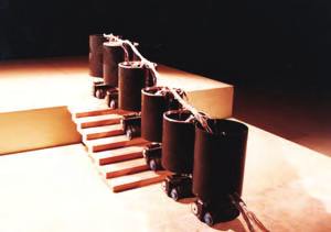
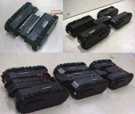
The concept of joining several small robots into a train to overcome larger obstacles was
used by researchers from Carnegie Mellon University in their Millibot Train (Brown et al.,
2002). This robot consists of seven electrically driven, very compact segments. The diameter
of the track sprockets is larger than the height of each segment, which allows the robot to
drive upside-down. Segments are connected by couplers for active connection and
disconnection, but the joints have only one DOF. Each joint is actuated by an electric motor
with a high-ratio harmonic gear and slip clutch. It provides sufficient torque to lift up the
three front segments. The robot has been demonstrated to climb up a regular staircase and
even higher steps. However, with only one DOF in each joint the vehicle is kinematically
limited.
A serpentine robot that uses tracks for propulsion and pneumatics for joint actuation is
MOIRA shown in Fig. 9 (Osuka & Kitajima, 2003). MOIRA comprises four segments, and
Fig. 9. Robot Moira from Osuka Lab.
each segment has two longitudinal tracks on each of its four sides, for a total of eight tracks
per segment. All tracks are driven from a single motor through the system of 4 bevel and 4
spiral gears and therefore they move in the same direction. With tracks on each side robot is
322
New Approaches in Automation and Robotics
insensitive for rollovers and with additionally cone shaped distal segments robot can dig
into the debris with obstacles touching it from all sides. The 2-DOF joints between segments
are actuated by pneumatic cylinders. Although with pneumatic cylinders MOIRA can lift up
its segments high enough to overcome obstacles, it can also decrease stiffness of actuators to
nicely conform to the ground, but we think that with very long joints this design is prone to
getting stuck on some narrow obstacles. Robot is controlled from the specially designed
control box containing 3 joysticks and several switches. There is also view from nose CCD
camera transmitted via USB.
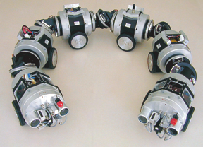
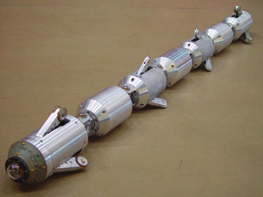
The newest construction from NREC (National Robotics Engineering Center) is Pipeline
Explorer – robot designed and built for inspection of live gas pipelines (Schempf et al.,
2003). This robot, shown in Fig. 10, has a symmetric architecture. A seven-element
articulated body design houses a mirror-image arrangement of locomotor (camera)
modules, battery carrying modules, and support modules, with a computing and electronics
module in the middle. The robot’s computer and electronics are protected in purged and
pressurized housings. Segments are connected with articulated joints: the locomotor
modules are connected to their neighbors with pitch-roll joints, while the others – via pitch-
only joints. These specially designed joints allow orientation of the robot within the pipe, in
any direction needed.
Fig. 10. Pipeline Explorer from NREC (reproduced from
http://www.rec.ri.cmu.edu/projects/explorer)
The locomotor module houses a mini fish-eye camera, along with its lens and lighting
elements. The camera has a 190-degree field of view and provides high-resolution color
images of the pipe’s interior. The locomotor module also houses dual drive actuators
designed to allow for the deployment and retraction of three legs equipped with custom-
molded driving wheels. The robot can sustain speeds of up to four inches per second. It is
fully untethered (battery-powered, wirelessly controlled) and can be used in explosive
underground natural gas distribution pipelines. Construction of robot naturally limits its
application to pipes of certain diameters.
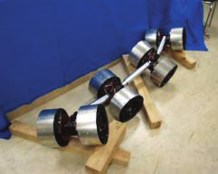
From 2002 to 2005 researchers from the Mobile Robotics Lab at the University of Michigan
introduced the whole family of hypermobile robots called Omnis, shown in Fig. 11. In the
OmniPede, the first one, they introduced three innovative functional elements: (1)
propulsion elements (here: legs) evenly located around the perimeter of each segment; (2)
pneumatic power for joint actuation; and (3) a single so called “drive shaft spine” that
transfers mechanical power to all segments from a single drive motor (Long et al., 2002).
From the study of the OmniPede, and from the observed shortcomings of this legged
propulsion prototype, they derived important insights about the design of serpentine