N
VOLTAGE
CONTROLLED
G
CONVERTER
G
RESET
DRIVER
A
LOADING
N
N
VOLTAGE
CONTROLLED
V
(L298N)
L
CURRENT
CURRENT
DEVICE
REF
A
A
LOADING
S
SENSOR
L
L
CURRENT
CURRENT
DEVICE
HOME
(LEM MODULES)
CONTROLLED
S
S
SENSOR
SERVOMOTOR
TORQUE
VOLTAGE SENSORS
LOADING
r
m (t)
SENSOR
VOLTAGE u , u
SERVOMOTOR
TORQUE
F1
F2
DEVICE
r
m (t)
SENSOR
D.C.
DIC
CURRENT
CURRENT SENSORS
i , i
TAHO
TS
F1
F2
(LEM MODULES)
TORQUE
D.C.
DIC
TAHO
TS
SM
(LOAD)
SENSOR
SM
(LOAD)
n( )
t
n( )
t
n( )
t m(t)
OPTICAL
CLD
n( )
t
n( )
t
n( )
t m(t)
M
SENSE
ENCODER
SM
TS
M
(LOAD)
M
SENSE
E
OPTICAL
E
A B N
n( )
t
E
OPTICAL
A
TIRO
ENCODER
A
A
TIRO
(f) (f)
STEPPER
ENCODER
S
SENSE
S
SERVOMOTOR
S
U
A B N
U
U
A B N
R
(f) (f)
R
SD
SENSE
R
(f) (f)
E
E
DISCRIMINATOR
E
D
D
SENSE
CW
CCW SENSE
D
SENSE
SD
SD
DISCRIMINATOR
S
SPEED
DISCRIMINATOR
S
(4f)
(4f)
S
SPEED
I
I
2
2
I
2
CW
(4f)
G
POSITION
CW
G
SPEED
(4f)
G
SPEED
N
{
N
{
N
{
SPEED
POSITION
POSITION
CCW
A
CCW
A
A
SENSE
SENSE
L
SENSE
L
L
S
S
TORQUE
S
TORQUE
TORQUE
Fig. 1. Remote control architecture.
A user can have access to the process and run an experiment in real time using Intranet and
Internet. The user can design and implement different control structures for electrical drive
systems employing SCADA software facilities or, for a given control structure, he is able to
Networked Control Systems for Electrical Drives
75
implement and test PID control algorithms and tuning procedures. SCADA software
enables programmers to create distributed control applications having supervisory facilities
and a Human-Machine Interface (HMI). As SCADA software, Lookout is used for the direct
structure and LabVIEW for the hierarchical structure. All external signals start and arrive at
HMI/SCADA computer.
The laboratory architecture allows running experiments while interacting with instruments
and remote devices. The I/O remote devices permit data acquisition from sensors and
supplying control signals for actuators, using A/D and D/A converters.
The NCS architecture offers the possibility to remotely choose a predefined control structure
to handle the electrical drives system variables or to design a new control application, using
SCADA software facilities.
In the first case, using the remote control architecture the students have the possibility to
practice their theoretical knowledge of electrical drive systems control in an easy way due to
process access by a friendly user interface. The second opportunity offered to the students is
to design a new networked control architecture which allows creating a new HMI/SCADA
application to remotely control a process, using Lookout and, respectively, LabVIEW
facilities (Carari et al., 2003).
The software architecture can be split in two parts: one concerns the control of the physical
process – server side and the other relates to the user interface – client side. The server runs
on the Microsoft Windows NT platform and is based on Lookout for direct structure and,
respectively, LabVIEW environment for hierarchical structure.
The server application contains the HMI interface and fulfils the following functions:
•
implements the control strategies;
•
communicates with I/O devices through object drives;
•
records the signals in a database;
•
defines the alarms.
The client process contains a HMI interface, similar or not with those from server
application, and has the following characteristics:
•
allows modifying remotely the parameters defined by application server through a Web
site;
•
communicates with server application;
•
displays the alarms defined by the server application.
The remote control architecture is mainly intended for educational use and it is employed
for electrical drive control course. The aim is to allow students to put in practice their
knowledge of electrical drives and control theory in an easy way without restrictions due to
process availability through laboratory and project works. One of the main features is the
possibility of integrating in the control loop of the remote process the user-designed
controller. The interface for the controller synthesis is very friendly.
2.2 NCS in the direct structure
The NCS in the direct structure is composed of a computer of the Intranet, called
HMI/Lookout that achieves the local communications with the process using Ethernet
protocols. The remote electrical drive system, a D.C. brush servomotor, is connected with
the communication module (CM) able to transfer data from/to I/O device to/from
HMI/SCADA computer via a communication system. The communication module and I/O
devices are implemented with National Instruments modules, FP1600 (Ethernet) for
76
New Approaches in Automation and Robotics
communication and, respectively, Dual-Channel Modules for I/O devices. The Lookout
environment has been chosen to implement HMI/SCADA application. For D.C. servomotor,
a cascade control structure is used in order to control the speed from the primary loop and
the current from the secondary loop. The current controller is locally implemented and the
speed controller is remotely implemented using Lookout environment. The cascade control
structure allows the monitoring of control loops variables and the command of the overload
at the servomotor shaft.
2.3 NCS in the hierarchical structure
Hierarchical structure is composed of a computer of the Intranet, called HMI/LabVIEW
with a PCI motion controller board (National Instruments PCI-7354) and Analog & Digital
I/O devices.
DSP controllers available today are able to perform the computation for high performance
digital motion control structures for different motor technologies and motion control
configuration. The level of integration is continuously increasing, and the clear trend is
towards completely integrated intelligent motion control (Kreidler, 2002). Highly flexible
solutions, easy parameterized and “ready-to-run”, are needed in the existent “time-to-
market” pressing environment, and must be available at non-specialist level.
Basically, the digital system component implements through specific hardware interfaces
and corresponding software modules, the complete or partial hierarchical motion control
structure, i.e., the digital motor control functionality at a low level and the digital motion
control functionality at the higher level (see Fig. 2).
Communication protocols
Reference generator
Motion Control
Speed control
Position control
Current control
Pulses control PWM
Motor Control
Real-time operating kernel
Digital
system
Fig. 2. Motion system structure hierarchy.
The National Instruments PCI-7354 controller is a high-performance 4-axis-stepper/D.C.
brush/D.C. brushless servomotors motion controller. This controller can be used for a wide
variety of both simple and complex motion applications. It also includes a built-in data
acquisition system with eight 16-bit analog inputs as well as a host of advanced motion
trajectory and triggering features. Through four axes, individually programmable, the board
can control independently or in a coordinated mode the motion. The board architecture,
which is build around of a dual-processors core, has own real-time operating system . These
board resources assure a high computational power, needed for such real-time control.
Three electrical drive systems, based on a unipolar or bipolar stepper servomotors, D.C.
brush servomotors and a D.C. brushless servomotors are linked to the remote control
architecture. The connection is achieved with the I/O devices from PCI motion controller
Networked Control Systems for Electrical Drives
77
board, which also contains a remote controller implemented using a DSP and real-time
operating system, as is presented in Fig. 3.
CPU (MC68331)
&
DSP (ADSP 2185)
Real-Time
IBM
Operating System
PC
Supervisory;
•
Trajectory Generation;
•
Communications.
•
Control Loop.
•
HMI-LabVIEW
Server
Watchdog
Application
FPGAs
Timer
Encoders;
•
CPU Operation Monitoring.
•
Motion I/O.
•
NI Motion Controller (PCI-7354)
Electrical Drives System
Fig. 3. Motion controller board structure.
Functionally, the architecture of the National Instruments PCI-7354 controller is generally
divided into four components (see Fig. 4):
•
supervisory control;
•
trajectory generator;
•
control loop;
•
motion I/O.
Supervisory Control
IBM
PC
ε*
To Drive
Trajectory Ω*
Analog
Control Loop
&
HMI-LabVIEW Generator
θ*
Digital
Server
I/O
From Feedback & Sensors
Application
NI Motion Controller (PCI-7354)
Fig. 4. Functional architecture of the NI PCI-7354.
Supervisory control performs all the command sequencing and coordination required to
carry out the specified operation. Trajectory generator provides path planning based on the
profile specified by the user, and control loop block performs fast, closed-loop control with
simultaneous position, velocity, and trajectory maintenance on one or more axes, based on
feedback signals.
The LabVIEW environment has been chosen to implement HMI/SCADA application. The
development environment used to complete the applications is LabVIEW 7.0, which beside
the graphic implementation that gives easy use and understanding takes full advantage of
the networking resources. Using NCS hierarchical structure, control architecture for stepper
78
New Approaches in Automation and Robotics
servomotors, D.C. brush servomotors and D.C. brushless servomotors supervisory was
developed which allows the following functions:
-open-loop control of stepper servomotors using constant frequency or prescribed profile
(trapezoidal or S-curve move profile, see Fig. 5);
Velocity
Velocity
[steps/s]
[steps/s]
t [s]
0
t [s]
0
a.
Trapezoidal.
b.
S-Curve.
Fig. 5. Move Profile.
•
closed-loop control of stepper servomotors (speed and position);
•
the operating mode of the stepper servomotors can be with full step, half step or
microstepping mode;
•
open-loop control or closed-loop control of D.C. brush servomotors;
•
self-commutation control of D.C. brushless servomotor speed, which allows very high
speeds;
•
sensorless control for D.C. brushless servomotor.
3. Session description
This section presents three examples to illustrate the manipulation of instruments and real
devices for low power electrical drives education on the Web. These examples exemplify the
laboratory works dedicated to control a D.C. brush servomotor electrical drives system and
a stepper servomotor electrical drives system.
3.1 NCS in the direct structure: D.C. brush servomotor electrical drives system
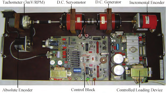
The set-up for D.C. brush servomotor control is presented in Fig. 6 and the layout can be
inspected in Fig. 1.
The set-up consists in a D.C. brush servomotor, a D.C. brush generator used as load, an
incremental encoder and a tachometer as speed transducer, a controlled loading device and
a control block which includes an analogical controller for current loop. The set-up is used
to illustrate cascade control and how this structure can reject the load disturbances. The
primary variable is the motor speed, the secondary is the armature current and the
disturbance is an overload introduced with a D.C. brush generator coupled on the
servomotor shaft. The user has to tune the two controllers of the speed and current loops in
order to obtain optimal performances and disturbance rejection.
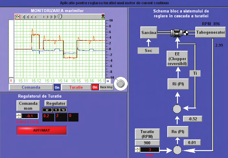
When the application is started, the main panel from Fig. 7 is displayed. The main panel
contains in the right side, the layout of the control system, real time data from the sensors
and actuator and allows the reference setting, the overload command, the choice of
operating mode: manual or automatic and the changing of the tuning parameters of the PI
speed controller (Baluta & Lazar, 2007).
Networked Control Systems for Electrical Drives
79
Fig. 6. D.C. brush servomotor electrical drives system.
Fig. 7. Main panel for D.C. brush servomotor electrical drives system.
All these commands can be done using the left down side of the main panel. In the left up
side, there is a monitor window, which allows the displaying of the main variables of the
control loops. The Monitor window has the possibility to represent only the selected signals
by using on/off buttons or to stop the variables displaying in order to analyse the signals or
to change the time scale through a potentiometer button. All control system real time data
are recorded in a database and can be employed for a future analysis (Baluta & Lazar, 2007).
80
New Approaches in Automation and Robotics
The remote control of the D.C. brush servomotors implements the following functions:
•
the reversible speed control;
•
the on-line tuning of the parameters of speed controller;
•
load command for servomotor shaft.
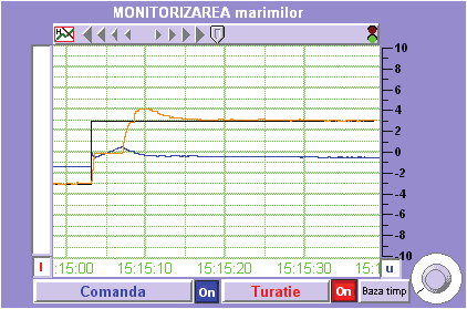
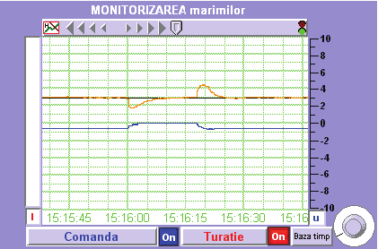
The monitor window of the main panel from Fig. 7 shows both the speed response for a
different set point step variations and the load rejection and the current evolution. Details
regarding disturbance rejection are given in Fig. 8. The numerical controller’s parameters
which have led to such results are Kr=0.2, Ti=2 and Td=0. Due to the well-chosen and
adjusted controller, the system’s response to a step variation of the set point is very good. At
the same time, a good compensation of the disturbance can be noticed (the load torque).
a. Step variation of the set point.
b. Load disturbance rejection.
Fig. 8. Monitoring panel (set point-black, speed-brown, armature current-blue).
3.2 NCS in the hierarchical structure: D.C. brush servomotor electrical drives system
The D.C. brush servomotor has the following features:
•
rating armature voltage Un=20V;
Networked Control Systems for Electrical Drives
81
•
rating armature current In=2A;
•
rating speed nn=2400 rpm;
•
armature winding resistance Ra=1.31 Ω;
•
armature winding inductance La=7.58 mH.
The D.C. brush servomotor is driven by a reversible chopper with the L292 specialized
integrated circuit (Baluta, 2004). The motor’s shaft is connected with an incremental optical
encoder that gives 1000 pulses/rev. (this means 4000 pulses/rev. at the output of the NI
PCI-7354 controller). The D.C. brush servomotor is loaded using a controlled loading device.
Among the features of the loading system, the authors emphasize (Baluta, 2004):
•
the possibility to load the electric drive motor with a reactive load torque in a wide
range of speed, including very low speeds;
•
the possibility to impose a constant load torque operation mode or an overload
operation mode.
The implemented control system uses the algorithm from Fig. 9, which allows to generate in
real-time the move trajectory and to change the motion parameters. In order to program the
motion control system, the developer employs LabVIEW environment with specific virtual
instruments for motion control from the FlexMotion library.
Read Maximum Velocity
Read Maximum Acceleration
Read Maximum Deceleration
Set Operation Mode
Read Final Position
Start Motion
Loop Waiting for Move Complete
Read (Update) Position and
and Move Constraints
Start Motion (Optional)
Perform Non-Motion
Measurement
Fig. 9. Position-based straight-line move algorithm.
Within such application, the user has the possibility to study either:
•
the command regimes in speed open-loop;
•
the position control regimes of the positioning system.
The graphic program associated to the first type of study is that shown in Fig. 10. It is
structured by means of a single while () loop, preceded by an initialization sequence
allowing the configuration of the system (selection of chopper control signal, setting of
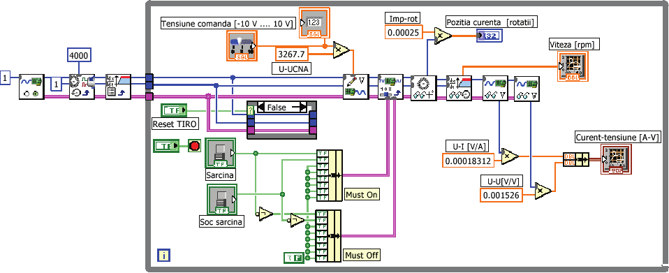
82
New Approaches in Automation and Robotics
optical encoder parameters, definition of the speed measurement units). The control
elements of the loop creates the possibility that the user could modify the chopper control
signal and/or to establish the servomotor loading degree. The measures acquired in view of
their graphical representation are the electrical ones (current in the armature winding and
supply modulated voltage of the armature winding) as well as the mechanical ones
(position and speed of the drive system). Leaving off the application is achieved explicitly,
by means the Stop push-button, available in the graphical user interface.
Fig. 10. LabVIEW diagram for the command regimes in speed open-loop.
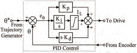
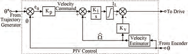
The vast majority of motion control algorithms employed in industrial applications are of
two forms (Ellis & Lorentz, 1999]:
•
the well-known PID position loop (Fig. 11a);
•
an average velocity loop cascaded with a position loop (Fig. 11b).
a. PID Servocontrol topology.
b. PIV. Servocontrol topology.
Fig. 11. Servocontrol topology.
Networked Control Systems for Electrical Drives
83
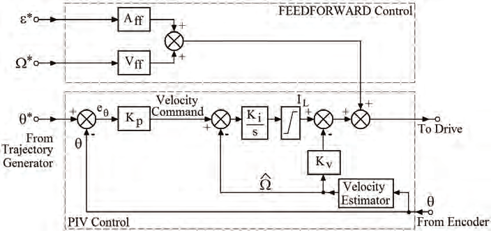
On the other hand, in order to achieve near zero following or tracking error, feedforward
control is often employed. A requirement for feedforward control is the availability of both
the velocity, Ω*(t), and acceleration, ε*(t), commands synchronized with the position
commands, θ*(t).
An example of how feedforward control is used in addition to the second servocontrol
topology is shown in Fig. 12. The National Instruments PCI-7354 controller can be
configured for any of the above servocontrol topologies.