

which implies that either the first row or first column are all you need to know to know all of ℋ.
Circulant matrices are a special case of Toeplitz matrices, which are constant along
diagonals. e.g. :
Tnk= t[ n− k]
Example 4.5.
Also, row n, column k element of ℋ is
()
ℋnk= h[( n− k)mod N]
where 0≤ n≤ N−1 and 0≤ k≤ N−1 and h is the signal corresponding to the first ( i.e. the zeroth!) column of ℋ .
Example 4.6.
N=2 ,
()
Example 4.7.
Apply a 3-point moving average smoother to a signal
.
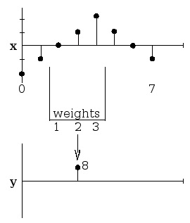

Figure 4.16.
ℝ8 .
In Figure 4.16,
()
y[ n]=1 x[( n−1)mod N]+2 x[ n]+3 x[( n+1)mod N]
()
The relationship between rows and columns of ℋ :
()
ℋnk= h[( n− k)mod N]
where n is the row, k is the column, and 0≤ n≤ N−1 and 0≤ k≤ N−1 .
Rows and columns run time in reverse order!!!


Example 4.8.
ℝ4
()
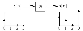
where the zeroth column,
, is the impulse response, h[ n] (Figure 4.17).
Figure 4.17.
Reponse to impulse at n=0 : 2 comes out, then 1, then 0, ….
In Equation, the zeroth row,
, is the time-reversed impulse response, h[– k] .
Upshot for LSI Systems
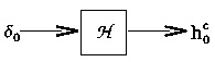
Figure 4.18.
The impulse response; the zeroth column of ℋ .
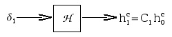
Figure 4.19.
The shifted impulse response. Here,
is a shifted impulse.
Figure 4.20.
The m-shifted impulse response. Here,
is an m-shifted impulse.


i.e. : if we input Figure 4.18 and measure output , we can place it in the zeroth column of ℋ and then replicate it with circular shifts to build the entire ℋ!!
Summary: LSI Systems and Imuplse Response
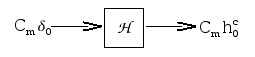
Given an LSI system (Figure 4.15), we can characterize it by the impulse response, h
Figure 4.21.
and build up ℋ with circular shifts of the zeroth column, h:
()
Then we can compute y for any input x∈ℂ N through
()
y= ℋx
Exercise 2.
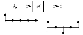
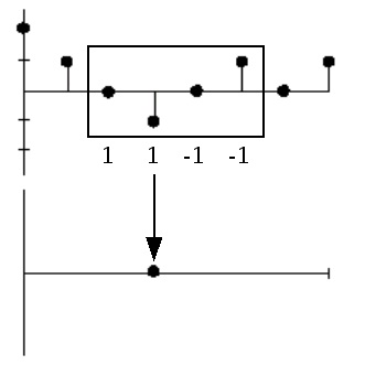
How to get the impulse response?
4-point edge detector for 8-point signals in complex space (Figure 4.21).
Figure 4.21.
h =
ℋ =
4.6. System Classifications and Properties*
Introduction
In this module some of the basic classifications of systems will be briefly introduced and the most
important properties of these systems are explained. As can be seen, the properties of a system
provide an easy way to separate one system from another. Understanding these basic difference's
between systems, and their properties, will be a fundamental concept used in all signal and system
courses, such as digital signal processing (DSP). Once a set of systems can be identified as sharing
particular properties, one no longer has to deal with proving a certain characteristic of a system
each time, but it can simply be accepted do the systems classification. Also remember that this
classification presented here is neither exclusive (systems can belong to several different
classifications) nor is it unique.
Classification of Systems
Along with the classification of systems below, it is also important to understand other
Continuous vs. Discrete
This may be the simplest classification to understand as the idea of discrete-time and continuous-
time is one of the most fundamental properties to all of signals and system. A system where the
input and output signals are continuous is a continuous system, and one where the input and
output signals are discrete is a discrete system.
Linear vs. Nonlinear
A linear system is any system that obeys the properties of scaling (homogeneity) and
superposition (additivity), while a nonlinear system is any system that does not obey at least one
of these.
To show that a system H obeys the scaling property is to show that
()
H( kf( t))= kH( f( t))
Figure 4.22.
A block diagram demonstrating the scaling property of linearity
To demonstrate that a system H obeys the superposition property of linearity is to show that
()
H( f 1( t)+ f 2( t))= H( f 1( t))+ H( f 2( t))
Figure 4.23.
A block diagram demonstrating the superposition property of linearity
It is possible to check a system for linearity in a single (though larger) step. To do this, simply
combine the first two steps to get
()
H( k 1 f 1( t)+ k 2 f 2( t))= k 2 H( f 1( t))+ k 2 H( f 2( t)) Time Invariant vs. Time Variant
A time invariant system is one that does not depend on when it occurs: the shape of the output
does not change with a delay of the input. That is to say that for a system H where H( f( t))= y( t) , H is time invariant if for all T
()
H( f( t− T))= y( t− T)
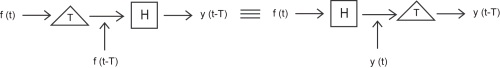
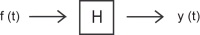

Figure 4.24.
This block diagram shows what the condition for time invariance. The output is the same whether the delay is put on the input or the output.
When this property does not hold for a system, then it is said to be time variant, or time-varying.
Causal vs. Noncausal
A causal system is one that is nonanticipative; that is, the output may depend on current and past
inputs, but not future inputs. All "realtime" systems must be causal, since they can not have future
inputs available to them.
One may think the idea of future inputs does not seem to make much physical sense; however, we
have only been dealing with time as our dependent variable so far, which is not always the case.
Imagine rather that we wanted to do image processing. Then the dependent variable might
represent pixels to the left and right (the "future") of the current position on the image, and we
would have a noncausal system.
(a) For a typical system to be causal...
(b) ...the output at time t 0 , y( t 0) , can only depend on the portion of the input signal before t 0 .
Figure 4.25.
Stable vs. Unstable
A stable system is one where the output does not diverge as long as the input does not diverge.
There are many ways to say that a signal "diverges"; for example it could have infinite energy.
One particularly useful definition of divergence relates to whether the signal is bounded or not.
Then a system is referred to as bounded input-bounded output (BIBO) stable if every possible
bounded input produces a bounded output.
Representing this in a mathematical way, a stable system must have the following property, where
x( t) is the input and y( t) is the output. The output must satisfy the condition
()
| y( t)|≤ My<∞
when we have an input to the system that can be described as
()
| x( t)|≤ Mx<∞
Mx and My both represent a set of finite positive numbers and these relationships hold for all of t .
If these conditions are not met, i.e. a system's output grows without limit (diverges) from a
bounded input, then the system is unstable. Note that the BIBO stability of a linear time-invariant
system (LTI) is neatly described in terms of whether or not its impulse response is absolutely
integrable.
4.7. Discrete Time Systems*
Introduction
As you already now know, a discrete time system operates on a discrete time signal input and
produces a discrete time signal output. There are numerous examples of useful discrete time
systems in digital signal processing, such as digital filters for images or sound. The class of
discrete time systems that are both linear and time invariant, known as discrete time LTI systems,
is of particular interest as the properties of linearity and time invariance together allow the use of
some of the most important and powerful tools in signal processing.
Discrete Time Systems

Linearity and Time Invariance
A system H is said to be linear if it satisfies two important conditions. The first, additivity, states
for every pair of signals x, y that H( x+ y)= H( x)+ H( y). The second, homogeneity of degree one, states for every signal x and scalar a we have H( ax)= aH( x). It is clear that these conditions can be combined together into a single condition for linearity. Thus, a system is said to be linear if for
every signals x, y and scalars a, b we have that
(4.32)
H ( a x + b y ) = a H ( x ) + b H ( y ) .
Linearity is a particularly important property of systems as it allows us to leverage the powerful
tools of linear algebra, such as bases, eigenvectors, and eigenvalues, in their study.
A system H is said to be time invariant if a time shift of an input produces the corresponding
shifted output. In other, more precise words, the system H commutes with the time shift operator
ST for every T∈Z. That is,
(4.33)
ST H = H ST .
Time invariance is desirable because it eases computation while mirroring our intuition that, all
else equal, physical systems should react the same to identical inputs at different times.
When a system exhibits both of these important properties it opens. As will be explained and
proven in subsequent modules, computation of the system output for a given input becomes a
simple matter of convolving the input with the system's impulse response signal. Also proven
later, the fact that complex exponential are eigenvectors of linear time invariant systems will
encourage the use of frequency domain tools such as the various Fouier transforms and associated
transfer functions, to describe the behavior of linear time invariant systems.
Example 4.9.
Consider the system H in which
(4.34)
H ( f ( n ) ) = 2 f ( n )
for all signals f. Given any two signals f, g and scalars a, b
(4.35)
H ( a f ( n ) + b g ( n ) ) ) = 2 ( a f ( n ) + b g ( n ) ) = a 2 f ( n ) + b 2 g ( n ) = a H ( f ( n ) ) + b H
for all integers n. Thus, H is a linear system. For all integers T and signals f,
(4.36)
for all integers n. Thus, H is a time invariant system. Therefore, H is a linear time invariant
system.

Difference Equation Representation
It is often useful to to describe systems using equations involving the rate of change in some
quantity. For discrete time systems, such equations are called difference equations, a type of
recurrence relation. One important class of difference equations is the set of linear constant
coefficient difference equations, which are described in more detail in subsequent modules.
Example 4.10.
Recall that the Fibonacci sequence describes a (very unrealistic) model of what happens when
a pair rabbits get left alone in a black box... The assumptions are that a pair of rabits never die
and produce a pair of offspring every month starting on their second month of life. This
system is defined by the recursion relation for the number of rabit pairs y( n) at month n
(4.37)
y ( n ) = y ( n – 1 ) + y ( n – 2 )
with the initial conditions y(0)=0 and y(1)=1. The result is a very fast growth in the sequence.
This is why we never leave black boxes open.
Discrete Time Systems Summary
Many useful discrete time systems will be encountered in a study of signals and systems. This
course is most interested in those that demonstrate both the linearity property and the time
invariance property, which together enable the use of some of the most powerful tools of signal
processing. It is often useful to describe them in terms of rates of change through linear constant
coefficient difference equations, a type of recurrence relation.
4.8. PROPERTIES OF THE DIGITAL
CONVOLUTION*
Commutativity
By a change of variable n− k= k, , or k= n− k, in the formula for convolution
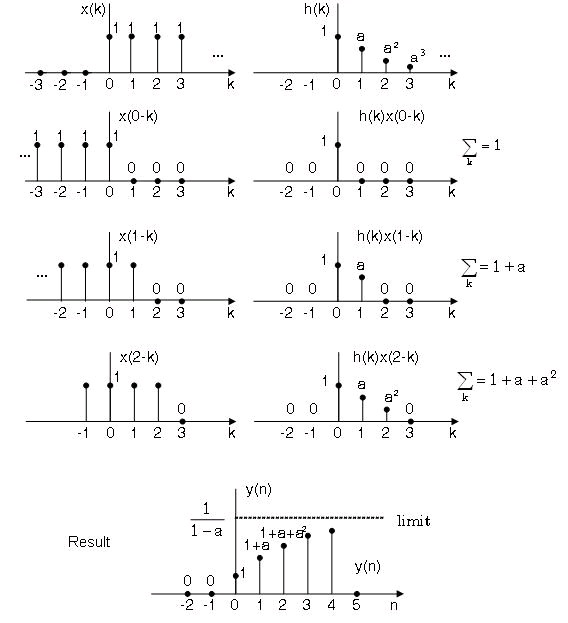


Figure 4.26.
and by replacing the temporary variable k’ by k, we get
That is the order of convolution is reversed. Thus we have two formulae of convolution:
()
and
()
In practive we usually let the longer sequence stay fixed, and shift the shorter one.
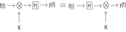
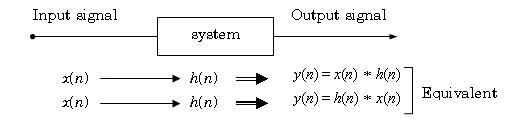
The commutative characteristic of convolution means that we can swap the input signal with the
impulse response of a system without affecting the output. This idea is depicted in Figure 4.27.
Figure 4.27.
Commutation between input signal and impluse response gives the same output
Associativity
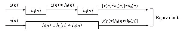
It can be shown that
()
[ x( n)∗ h 1( n)]∗ h 2( n)= x( n)∗[ h 1( n)∗ h 2( n)]
Figure 4.28 shows the system meaning of the associativity, where two systems in series (in
cascade) can be replaced by only one whose impulse response is the convolution of the two
individual impulse responses.
Figure 4.28.
Impluse response of two systems in cascade
Example 4.11.


Two systems in cascade have impulse responses
Find the overall impulse response.
Solution
First ∣ a∣ and ∣ b∣ should be smaller than 1 to ensure the convergence of the sequences. Notice that
both impulse responses are causal. The overall impulse response is
The actual limits of summation are k=0 and k= n(see The Section Called “Impulse Response For
Causal System And Signal” later), hence
Using the formula of finite geometric series.
()
here x= a/ b, we get
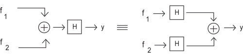
Distributivity
It can be shown
()
x( n)∗[ h 1( n)+ h 2( n)]= x( n)∗ h 1( n)+ x( n)∗ h 2( n) The system meaning is illustrated in Figure 4.29 where two systems connected in parallel can be
replaced by one whose impulse response is the sum of the two ones.
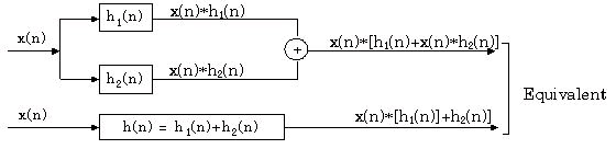


Figure 4.29.
Impulse response of two systems in paral