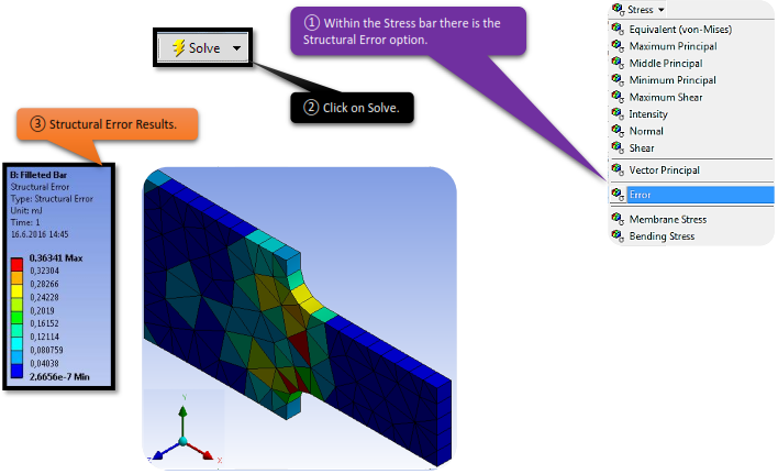
In this chapter we are interested to know the concepts of Finite Element Simulation, like “Stress Discontinuity”, “Structural Error”, “Stress Singularity”, “Finite Element Convergence”.
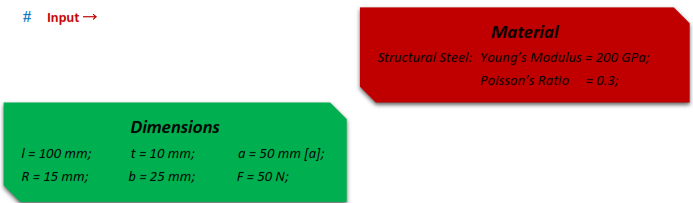
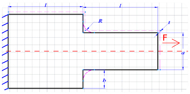
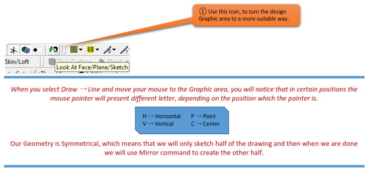
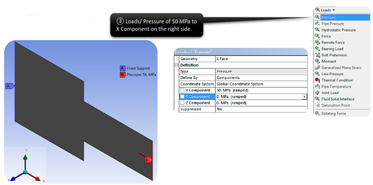
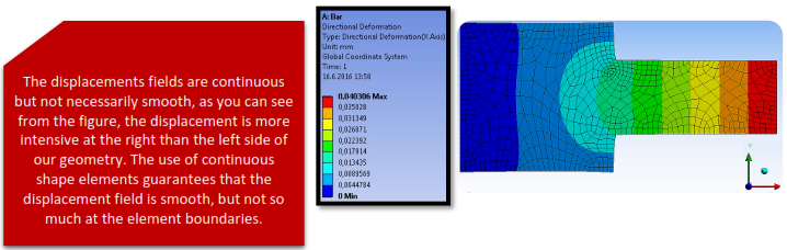
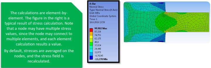
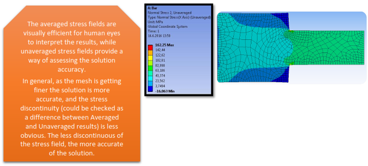
To demonstrate this concepts we are going to use a Plate geometry with notch, which is made out of steel and has the given dimensions. The bar has Fixed Support on the left side and is subject to a tension of 50MPa on the right side.
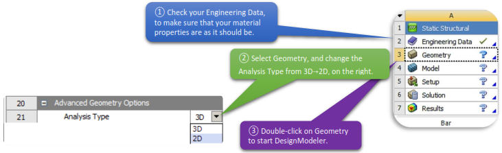
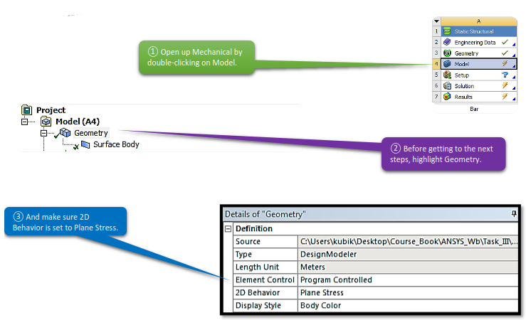
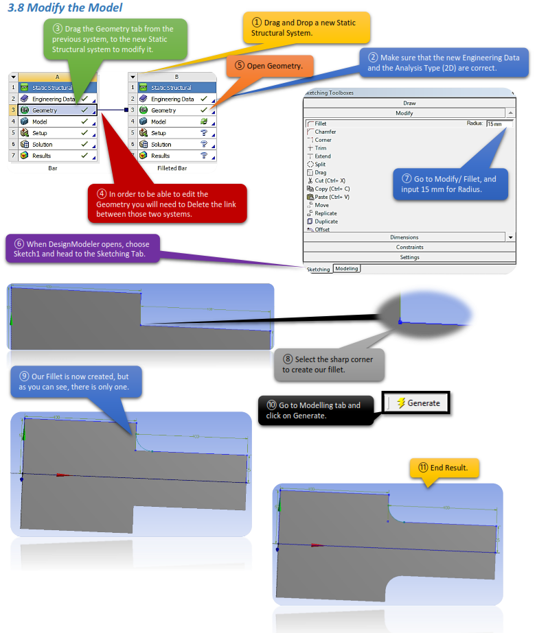
 Launch Workbench, create a Static Structural system by choosing it from the list on the left (toolbox). Save the project before we begin, to an appropriate location and name.
As soon as DesignModeler opens, go to Units and select Millimeters.
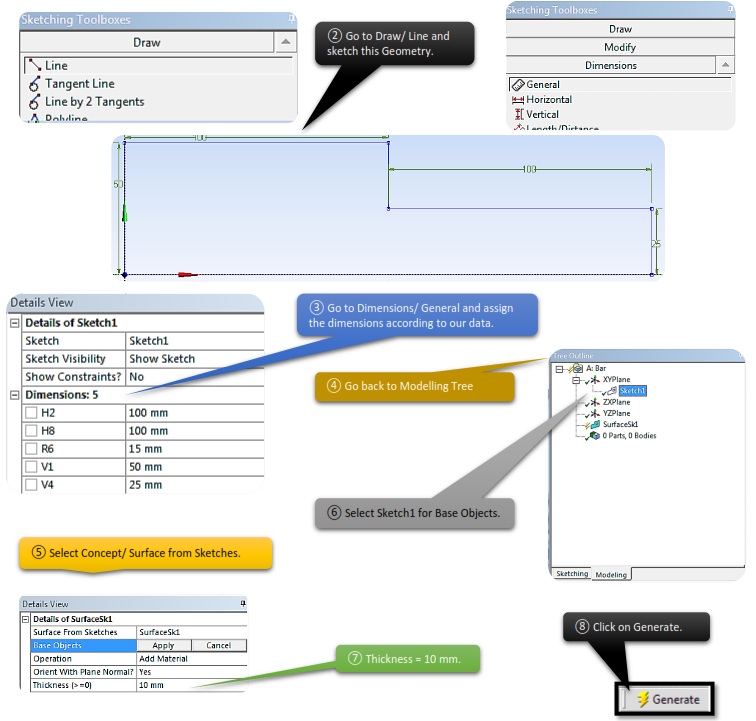
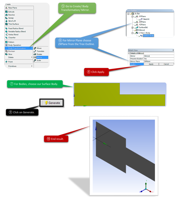
Let’s start creating our Geometry. Choose XYPlane as your sketch plane, open Sketching tab and create our Plate Bar.
3.8.1 Set Up New Supports, Loads
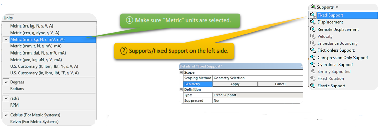
Make sure you got the correct Units selected in the Unit tab. Specify fixed support on the left edge and horizontal force of 50 MPa on the right edge.
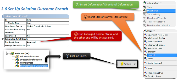
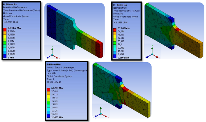
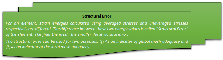
Insert Direction Deformation and two Normal Stresses (Averaged and Unaveraged), under the solution branch.
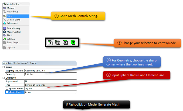
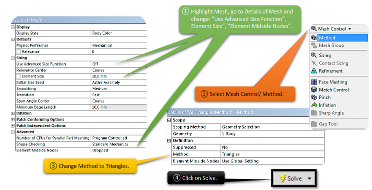
3.8.2 Set Up New Mesh Controls
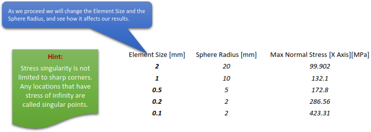
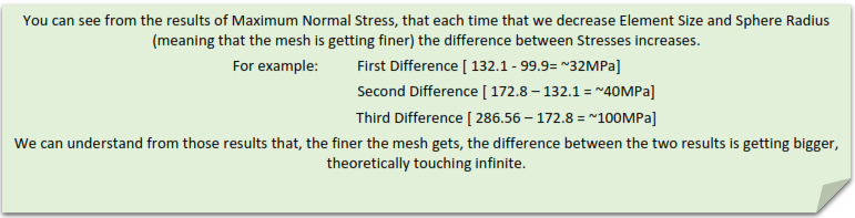
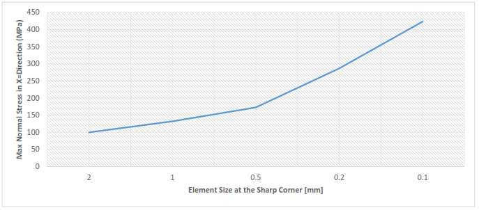
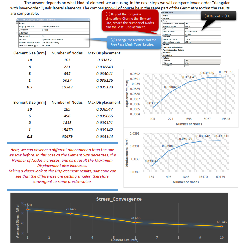
One of the core concepts of the finite element method is that, as mentioned, the finer the mesh, the more accurate the solution. Ultimately, the solution will reach the analytical solution. But how fast does it approach that solution? This is what we want to answer in this part of the chapter.
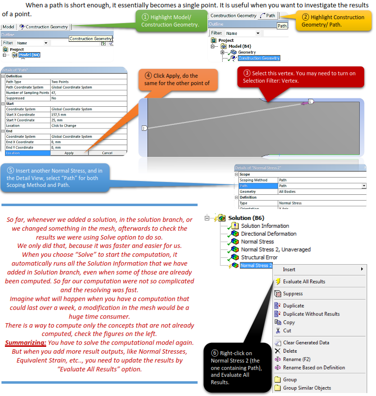
If we want to see how the stress concentrates in a specific area, we will need to create a path and then we will investigate the stresses along that path. Path command is also useful to make finer mesh in that specific area.
A path can be defined by two points, or an edge. Coordinates of the points can be either picked from the model or typed in the Details View.
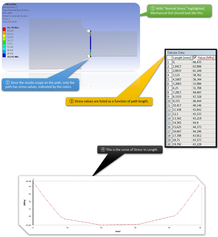
Any result objects can scope on a path. After solving, a result vs path data table along with a graph will be generated.