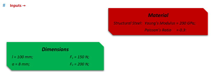
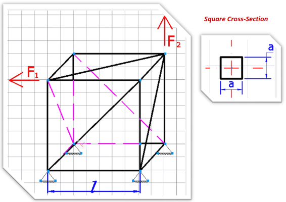
In this chapter we are asked to create a 3D Cube Beam System. The Cube Beam System has a square cross-section which is given below.
As we progress forward to more complicated tasks/geometries, the steps that we were explaining so detailed in the previous chapters won’t be explicated as much.
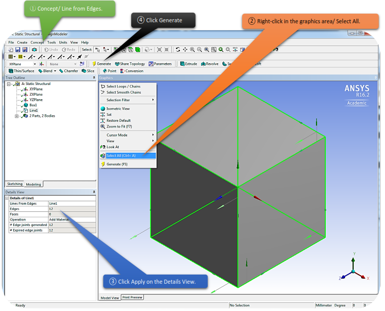
 The Lines From Edges feature allows the creation of Line Bodies in ANSYS DesignModeler that are based on existing model edges. The feature can produce multiple line bodies, depending on the connectivity of the selected edges and faces. Select 3D model edges, and faces through two Apply/Cancel button properties.
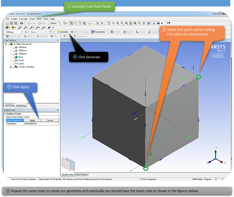
The Lines From Points feature allows the creation of Line Bodies in ANSYS DesignModeler that are based on existing points. Points can be any 2D sketch points, 3D model vertices, and point feature points (PF points). The feature's selections are defined by a collection of point segments. A point segment is a straight line connecting two selected points. The feature can produce multiple line bodies, depending on the connectivity of the chosen point segments. The formation of point segments is handled through an Apply/Cancel button property.
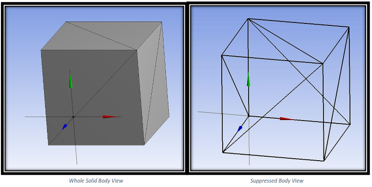
After you are done sketching, right-click on Solid  choose suppress body and you should have the same looks as above.
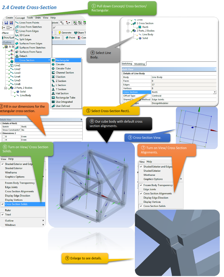
Cross-Section Alignments
The default cross section alignments usually need to be adjusted so that they are consistent with the reality. In this chapter we decided to leave them default. In other words cross section alignments do not affect the structural response too much in this case.