
# The ANSYS Workbench represents more than a general purpose engineering tool.
# These tutorials are designed to introduce you to
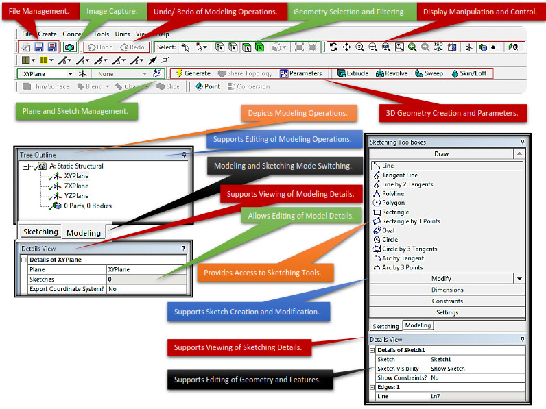
# Sketching Mode:
# Modeling Mode:
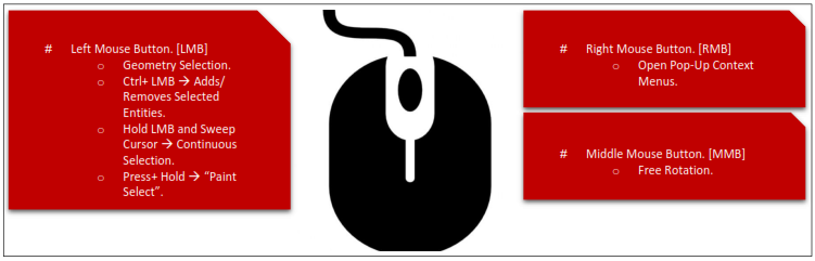
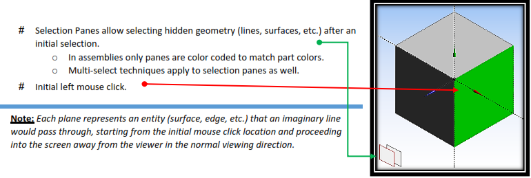
# Model features are identified by graphically picking them using the left mouse button.
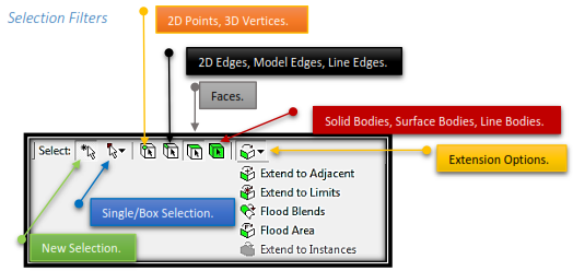
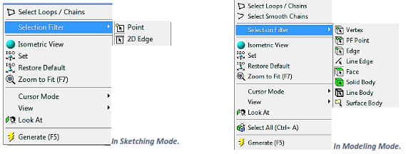
# Feature selection is done by activating one of the selection filters from the menu bar or from pop-up menus using the right mouse button.
# In selection mode, the cursor changes to reflect current selection filter.
# Adjacent and Flood Selections extend selections to adjacent areas. Additional information can be found in the ANSYS Workbench Help (documentation).
# Selection filters can also be set using pop-up menus (right mouse button in the Model View).
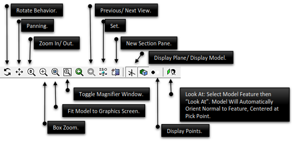
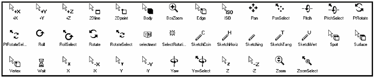
# While in Select Mode:
# While in Rotate, Pan or Zoom Mode:
# Mouse Cursor is Context Sensitive.
ANSYS Workbench integrates multiple applications into a single seamless project flow, where individual cells can obtain data from and provide data to other cells. As a result of this flow of data, a cell’s state can change in response to changes made up to the project. ANSYS Workbench provides visual indications of a cell’s state at any given time via icons on the right side of each cell.
Cell states can be divided into the following categories: 
 Unfulfilled
Required upstream data does not exist. Some applications may not allow you to open them with the cell in this state. For example, if you have not yet assigned a geometry to a system, all downstream cells will appear as unfulfilled, because they cannot progress until you assign a geometry.
Refresh Required 
Upstream data has changed since the last refresh or update. You may or may not need to regenerate output data. When a cell is in a Refresh Required state, you can Edit the cell, Refresh the data, Update Upstream Components, or Update the cell.
The advantage to simply refreshing a cell rather than performing a full update is that you can be alerted to potential effects on downstream cells before updating and can make any necessary adjustments. This option is especially useful if you have a complex system in which an update could take significant time and/or computer resources.
Attention Required 
All of the cell’s inputs are current; however, you must take a corrective action to proceed. To complete the corrective action, you may need to interact with this cell or with an upstream cell that provides data to this cell. Cells in this state cannot be updated until the corrective action is taken.
This state can also signify that no upstream data is available, but you can still interact with the cell. For instance, some applications support an “empty” mode of operation, in which it is possible to enter the application and perform operations regardless of the consumption of upstream data.
Update Required 
Local data has changed and the output of the cell needs to be regenerated.
Up to Date 
An Update has been performed on the cell and no failures have occurred. It is possible to edit the cell and for the cell to provide up-to-date generated data to other cells.
Input Changes Pending 
The cell is locally up-to-date but may change when next updated as a result of changes made to upstream cells.
Interrupted, Update Required 
Indicates that you have interrupted the solution during an update, leaving the cell paused in an Update Required state.
This option performs a graceful stop of the solver, which will complete its current iteration; although some calculations may have been performed, output parameters will not be updated. A solution file will be written containing any results that have been calculated. The solve will be resumed with the next update command.
Interrupted, Up to Date 
Indicates that you have interrupted the solution during an update, leaving the cell in an Up-to-Date state.
This option performs a graceful stop of the solver, which will complete its current iteration; output parameters will be updated according to the calculations performed thus far and a solution file will be written. You can use the solution for post processing (to look at the intermediate result, for example). Because the cell is already up-to-date, it will not be affected by a design point update; to resume the solve, right-click and select the Continue Calculation option.
Pending 
Signifies that a batch or asynchronous solution is in progress. When a cell enters the Pending state, you can interact with the project to exit ANSYS Workbench or work with other parts of the project. If you make changes to the project that are upstream of the updating cell, then the cell will not be in an up-to-date state when the solution completes.
Refresh Failed, Refresh Required 
The last attempt to refresh cell input data failed and the cell remains in a refresh required state.
Update Failed, Update Required
The last attempt to update the cell and calculate output data failed and the cell remains in an update required state.
Update Failed, Attention Required 
The last attempt to update the cell and calculate output data failed. The cell remains in an attention required state.
If an action results in a failure state, you can view any related error messages in the Messages view by clicking the Show Messages button on the lower right portion of the ANSYS Workbench tab.