 These parts will be transferred to Design Simulation as parts consisting of multiple bodies (volumes), but Shared Topology.
 Tools Form New Part.
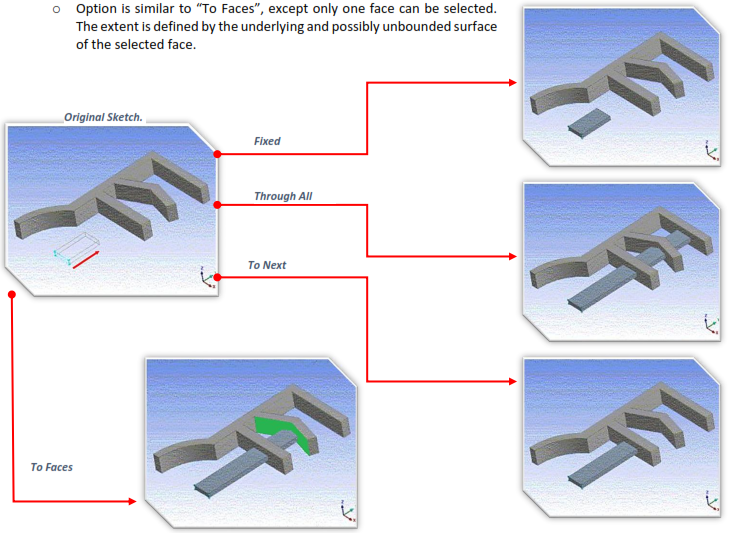
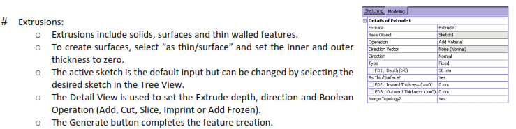
# Fixed:
 Fixed extents will extrude the profiles the exact distance specified by the depth property. The feature preview shows an exact representation of how the feature will be created.
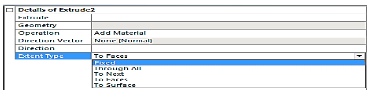
# Through All Type:
Will extend the profile through the entire model.
When adding material the extended profile must fully intersect the model.
# To Next:
Add will extend the profile up to the first surface it encounters.
Cut, Imprint and Slice will extend the profile up to and through the first surface or volume it encounters.
# To Faces:
Allows you to extend the Extrude feature up to a boundary formed by one or more faces.
For multiple profiles make sure that each profile has at least one face intersecting its extent. Otherwise, an extent error will result.
The “To Faces” option is different from “To Next”. To Next does not mean “to the next face”, but rather “through the next chunk of the body”.
The “To Faces” option can be used with respect to faces of frozen bodies.
# To Surface:
# Sweep:
Scale: Tapers or expands the profile along the path of the sweep.
Turns: Twists the profile as sweeps along the path.
A negative value for Turns will make the profile rotate about the path in the opposite direction.
Path Tangent: Reorients the profile as it is swept along the path to keep the profile in the path’s tangent direction.
Global: The profile’s orientation remains constant as it is swept along the path, regardless of the path’s shape.
# Skin/ Loft:
A profile is a sketch with one closed or open loop or a plane from a face.
All profiles must have the same number of edges.
Open and closed profiles cannot be mixed.
All profiles must be of the same type.
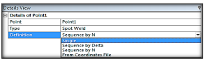
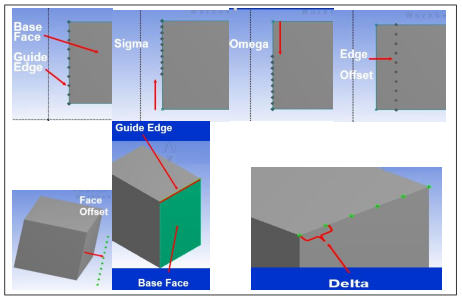
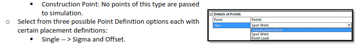
# Point:
Spot Weld: Used for “welding” together otherwise disjointed parts in an assembly.
Point Load: Used for “hard points” (nodal points) in the analysis.
Sequence By Delta -- > Sigma, Offset, Delta.
Sequence By N -- > Sigma, Offset, N, Omega.
From Coordinates File -- > Formatted text file, similar to 3D curve.
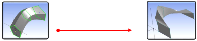
# Examples: