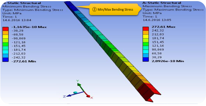
The purpose of this chapter is to find out the deformation of the beam and the displacement of its end point. Furthermore we will examine, how the stress will look like, when a loading by some specific weight, defined by the force.
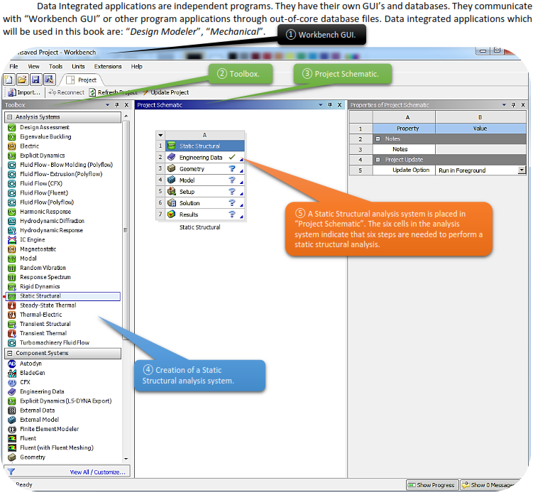
Native applications are directly supported in “Workbench GUI”, their program codes and database blind together. Native applications which will be used to this book are: “Project Schematic”, “Engineering Data”, and “Design Exploration”.
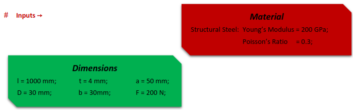
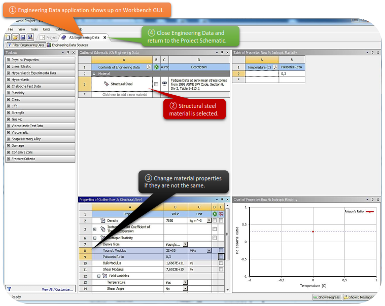
Double clicking to “Engineering Data” cell, will start Engineering Data application, where we want to specify our material properties. In this task our material is made by steel [Young’s Modulus= 200GPa, Poisson’s Ratio= 0,3] and as we can see, we don’t have to make any changes, as the default material properties of structural steel match with our requirements.
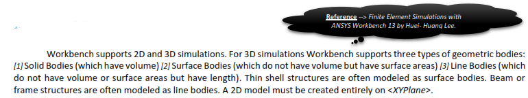
Workbench supports 2D and 3D simulations. For 3D simulations Workbench supports three types of geometric bodies: [1] Solid Bodies (which have volume) [2] Surface Bodies (which do not have volume but have surface areas) [3] Line Bodies (which do not have volume or surface areas but have length). Thin shell structures are often modeled as surface bodies. Beam or frame structures are often modeled as line bodies. A 2D model must be created entirely on <XYPlane>.
1.4.2 More on Geometric Modeling
Creating a geometric model is sometimes complicated and not as trivial as that in our first task. However it often can be viewed as a series of two-step operations as demonstrated in this case: Drawing a sketch and then using the sketch to create a 3D body by one of the techniques provided by Design Modeler such as extrusion, revolution, sweeping, skinlofting, etc.
Geometric modeling is the first step towards the success of simulations. For an engineer to be successful in simulation he/she must be proficient enough in geometric modeling.
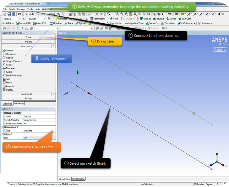
 Time to focus on our task and get more specific in certain commands of the Design Modeler application.
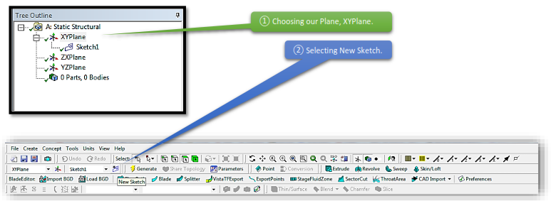
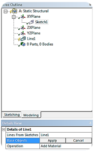
Now you can create a line with the given dimensions in the newly created “Sketch 1”.

The procedure that Workbench solves a problem can be viewed as two major steps:  Establishing a set of equations that govern the behavior of the problem and ② Solving the equations. The problem domain (i.e. the geometric model) is usually so complicated that it is almost impossible to establish and solve the governing equations directly. A core idea in the finite element method is to divide the entire problem domain into many smaller and simpler domains called “the finite elements”. The elements are connected by nodes. The governing equations for all elements will be solved simultaneously.
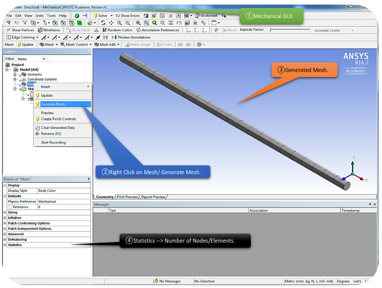
The dividing of geometric model into elements is called meshing and the collection of the elements is called the finite element mesh or sometimes called the finite element model. Strictly speaking, a finite element model should mean a finite element mesh PLUS it’s environment conditions.

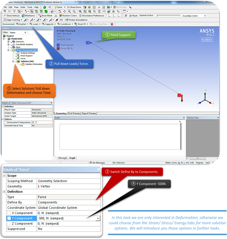
In the real world, all things are part of the world and they interact with each other. When we take an object apart for simulation, we are cutting it away from the rest of the world. The cutting surfaces of the model is called the boundary of the model. Where we cut the boundary is arbitrary – as long as we can specify the boundary conditions on all of the boundary surfaces. In Workbench all conditions affecting the response of the model are called the environment conditions which include boundary conditions. Strictly speaking, environment conditions include conditions that are not specified on the boundaries, for example, temperature changes over the entire body (not just on the boundary). In Workbench we don’t use the term “boundary conditions”, instead we will use the term “environment conditions”, which includes boundary and non-boundary conditions.
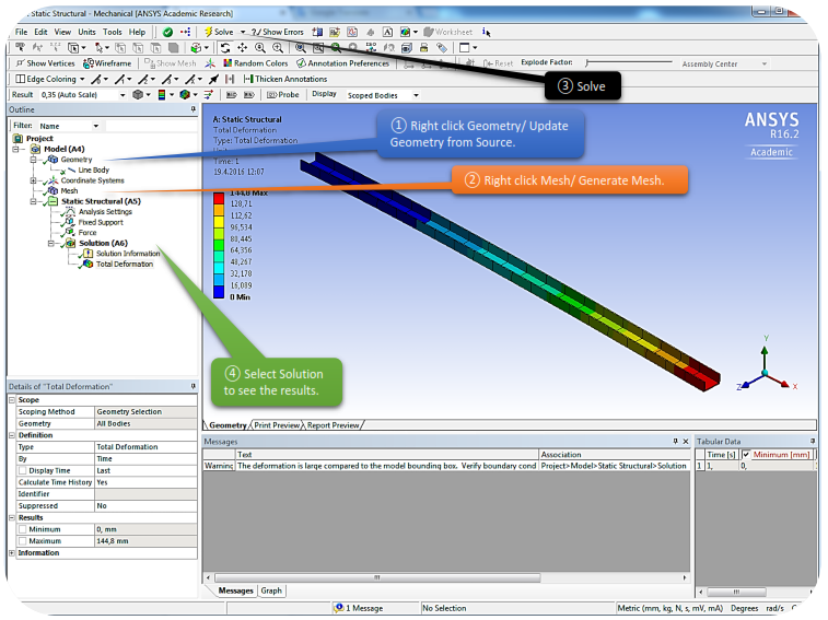
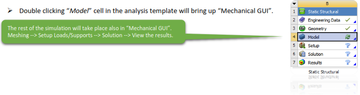
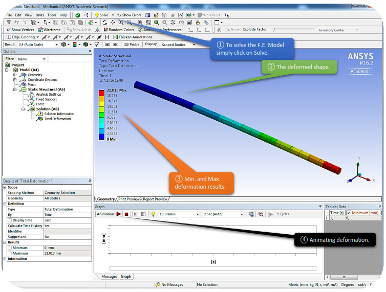
To solve a finite element model, simply click <Solve> in Mechanical GUI. The solution procedure is entirely automatic. The time to complete a simulation depends on the problem size and complexity. After the solution, the numerical results are stored in a database.
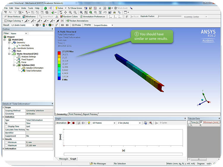
After the solution, numerical results are stored in databases, they can be viewed upon your request. In our case we are most concerned about the vertical deflection. The deformation also can be animated in the GUI. Note that the deflection is measured at the tip.
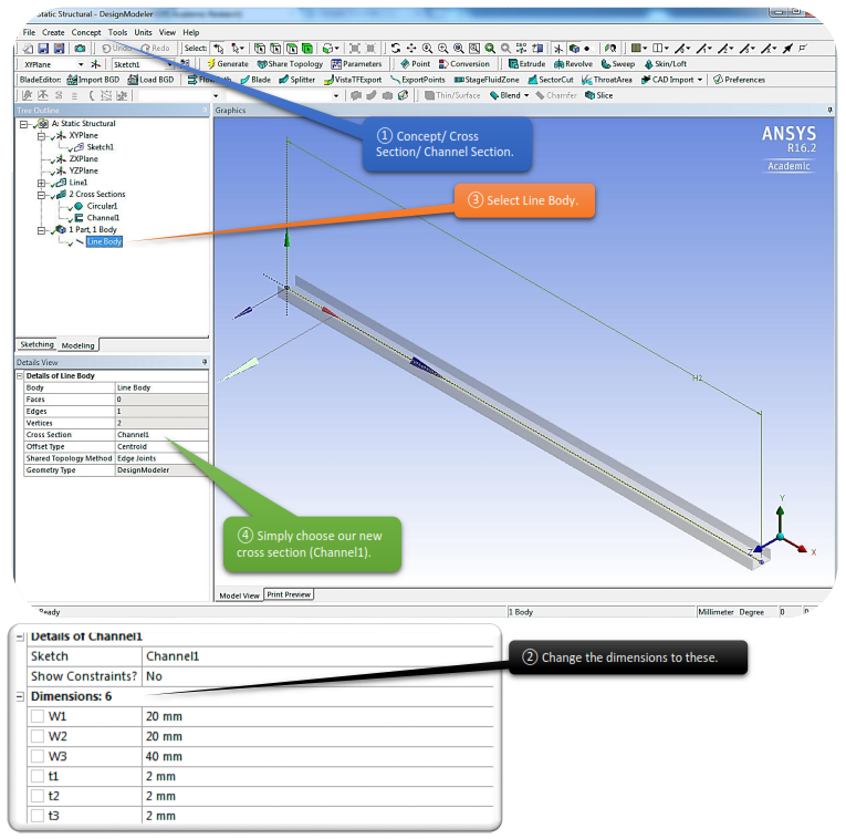
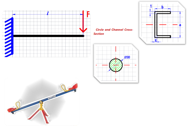
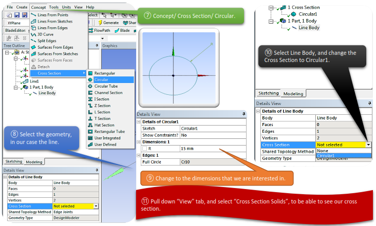
In order to change the type of our cross section, we have to go back to Design Modeler and add one more type of cross section.
Note: We don’t have to close Mechanical GUI, just Alt+Tab back to Geometry Mode.