3.4. Generating Schematic Reports and Annotation in
National Instruments Multisim*
Schematic Reports and Annotation
Multisim allows you to generate a number of reports: Bill of Materials (BOM), Component Detail Report, Netlist Report, Schematic Statistics, Spare Gates and the Cross Reference Report. A BOM lists the components used in your design and therefore provides a summary of the components needed to manufacture the circuit board. Information provided in the Bills of Materials include:
The Component Detail Report shows all information stored in the Multisim database for a particular component.
The Netlist Report provides the following circuit connectivity information for each component:
The Cross Reference Report provides a detailed list of all components and their locations in the design.
The Schematic Statistics Report provides the quantity of the following in a circuit:
The Spare Gates Report lists unused gates on multisection components. Note: Multisim provides a gate optimizer which will automatically and efficiently pack multisection parts onto the minimum number of chips. To run the gate optimizer select Tools/Rename/Renumber Components and then select Gate Optimizer.
Graphical Annotation
Multisim provides an easy method for graphically annotating your circuits. The Graphic Annotation toolbar allows placement of the following items: text, lines, multilines, rectangles, ellipses, arcs, polygons, pictures, and comments. To place graphical elements without using the toolbar, right-click on the schematic and select Place Graphic.
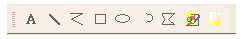
Figure 3.7.
Graphical Annotation Toolbar
Circuit Description Box
In addition to adding text to a particular portion of a circuit, you can add general descriptions to your circuit using the Circuit Description Box. You can also place bitmaps, sound and video in the Circuit Description Box.
The contents of the Circuit Description Box are viewed in the top pane of the Circuit Description Box window (select View/Circuit Description Box). To edit the contents of the Circuit Description Box, select Tools/Description Box Editor.
Title Blocks
A powerful title block editor allows you to create customized title blocks. If desired, a title block can be included on every page of your design.
Various fields in the title block are automatically filled in depending upon the context and various document properties. When designing the title block, you choose one of the pre-defined fields or a custom field. You choose appropriate fonts depending upon your language of preference. To edit an existing, or to create a new title block, select Tools/Title Block Editor.
Title blocks can include elements such as text, lines, arcs, Bezier curves, rectangles, ovals, arcs, bitmaps, and so on.
To place a title block, select Place/Title Block. The title block can be automatically placed in any corner by right-clicking on the title block and selecting Move To. To populate fields of each title block, simply double-click the title block.
Schematic Transfer to Ultiboard and Other Packages
Multisim includes a single-click feature which will transfer the current design to an installed copy of Ultiboard. Select Transfer/Transfer to Ultiboardto initiate the PCB design process. Designs can be easily forward and back-annotated using the same Transfer menu.
In addition to a transfer mechanism between Multisim and Ultiboard, designers also have the option to transfer designs to one of several other PCB layout packages. Note: Transferring designs to 3rd party layout packages may require matching Multisim components to components in the database of the chosen PCB layout program.
Solutions