Chapter 4. Simulation
4.1. Simulating Circuits using the SPICE in National
Instruments Multisim*
Simulation Overview
While a good design naturally follows from quality schematics, truly great designs can made with the help of simulation. Multisim provides powerful simulation capabilities and features which are simply unavailable in other EDA packages.
Simulating a design can result in fewer design iterations and less chance of errors in the prototype stage of product development. When a design is simulated at the front end of the design process, the number of design cycles can be significantly reduced.
In addition to a world-class SPICE simulator, Multisim also includes XSPICE simulation, enabling fast simulation of digital other components.
Patented co-simulation techniques allow designers to simulate VHDL modeled components along with the rest of a circuit. With MultiMCU, certain microcontrollers can be simulated in the very same mixed-mode environment. MultiMCU is not available for all versions of Multisim.
Using the Interactive Simulator
To begin a simulation, ensure that the circuit has all the necessary prerequisites. All circuits must include a ground reference, and a source. Once the circuit is ready for simulation, click the Run / Stop Simulation button or press F5. An interactive circuit simulation will begin.

Figure 4.1.
Run/Stop Simulation Button
The settings that are used for interactive simulation can be viewed and modified by selecting Simulate/Interactive Simulation Settings.Figure 1 below illustrates some of the settings available for interactive simulation. The default end time for the simulation is 1e+30 seconds, or around 3.17e+30 billion years. By default time steps will be generated automatically.
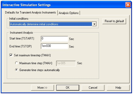
Figure 4.2.
Interactive Simulation Settings
To view results of this simulation, the measurement probe

Figure 4.3.
The Measurement Probe
can be used dynamically. Simply click on the probe icon and the mouse cursor will turn into a probe. The mouse can then be moved over any net to view the following metrics:
Virtual instruments can also display simulation results. Virtual instruments are covered later in this section.
Multisim also provides more traditional SPICE analyses, which are run through the Grapher/Analyses List toolbar button, or by selecting Simulate/Analyses. Analyses are described in greater detail later in this section.

Figure 4.4.
Grapher/Analyses List toolbar button
Handling Simulation Errors
Sooner or later, even the most experienced SPICE users will run into a SPICE simulation error.
Multisim includes a simulation advisor to help discover and fix the source of troubling errors.
When an error message appears such as the one in Figure 5, click the Adviser button to access the available help.
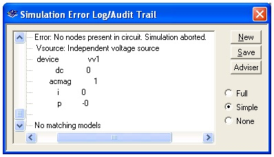
Figure 4.5.
Simulation Error Log Dialog Box
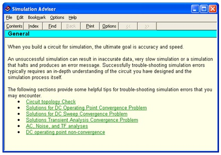
Figure 4.6.
Simulation Advisor
Two of the most often encountered errors are timestep errors, and singular matrix errors. below provides the most common solutions to these simulation errors.
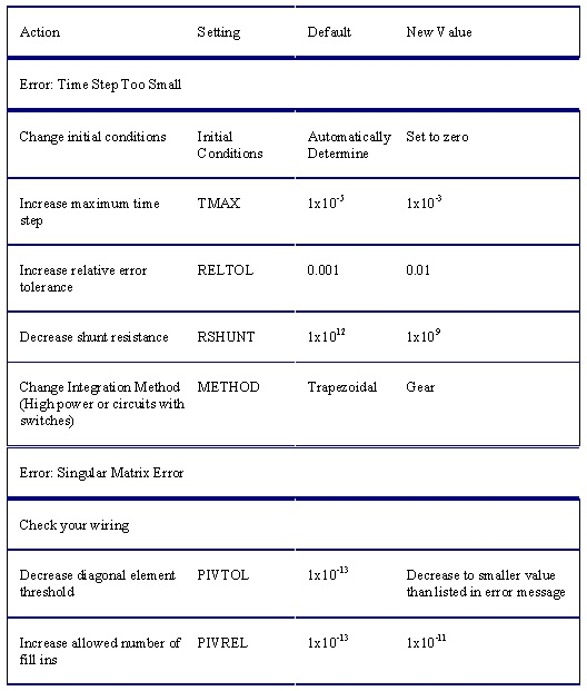
Figure 4.7.
Common Solutions to Simulation Errors