4.2. Instrumenting a Circuit Simulation in National
Instruments Multisim*
Instrumenting a Simulation in MultiSim
Virtual instruments are components in Multisim which model real-world benchtop instruments.
Examples of virtual instruments in Multisim include Oscilloscopes, Function Generators, Network Analyzers, and Bode Plotters.
Virtual instruments provide designers with an easy and intuitive method for interacting with their circuits as they would in a testing or prototyping phase.
In addition to the provided virtual instruments, designers with familiar with National Instruments LabVIEW can create their own custom instruments from scratch. For example, one could create a custom noise generator to model electromagnetic interference.
Custom virtual instruments written in NI LabVIEW can also acquire real-world data and use the data to drive simulations, and can send generated data to analog output hardware, allowing simulated data to control real-world devices. The LabVIEW development suite is required to create custom LabVIEW instruments, but not necessary to run existing LabVIEW based instruments.
To place a virtual instrument, select the desired instrument from the Instruments toolbar (Figure 1). To view the front panel of the instrument, double-click on the instrument icon. Make connections to the terminals of the instrument icon as you would to any other component.
Multisim also provides designers with simulated benchtop instruments. These are instruments such as the Tektronix TDS 2024 Oscilloscope. They will look and operate exactly according to the manufacturers’ user manuals.

Figure 4.8.
Instruments Toolbar
A single circuit can have multiple instruments attached to it, including (for most tiers) multiple instances of the same instrument. In addition, each circuit window can have its own set of instruments. Each instance of any instrument is configured and connected independently.
An overview of the more common instruments is included in this section. For more detailed information on how to use each instrument, consult the Multisim User Guide or helpfile.
Multimeter
Use the multimeter to measure AC or DC voltage or current, and resistance or decibel loss between two nodes in a circuit. The multimeter is auto-ranging, so a measurement range does not need to be specified. Its internal resistance and current are preset to near-ideal values, which can be changed.

Figure 4.9.
Multimeter Schematic Symbol

Figure 4.10.
Multimeter Front Panel
Function Generator
The function generator is a voltage source that supplies sine, triangular or square waves. It provides a convenient and realistic way to supply stimulus signals to a circuit. The waveform can be changed and its frequency, amplitude, duty cycle and DC offset can be controlled. The function generator's frequency range is great enough to produce conventional AC as well as audio-and radio-frequency signals.
The function generator has three terminals through which waveforms can be applied to a circuit. The common center terminal provides a reference level for the signal.

Figure 4.11.
Function Generator Schematic Symbol

Figure 4.12.
Function Generator Front Panel
Oscilloscopes
Multisim includes several varieties of oscilloscopes. All of the scopes can be controlled like real-world oscilloscopes. Horizontal timing and vertical voltages parameters can be adjusted. Triggering levels, and types are also selectable. Data from the Multisim-exclusive oscilloscopes is available in the Grapher after the interactive simulation has completed by selecting View/Grapher.
Multisim provides the following oscilloscopes:
-
2-Channel.
-
4-Channel.
-
Agilent 54622D Mixed Signal Oscilloscope.
-
Tektronix TDS 2024 Four Channel Digital Storage Oscilloscope.

Figure 4.13.
Oscilloscope Schematic Symbol

Figure 4.14.
Oscilloscope Front Panel
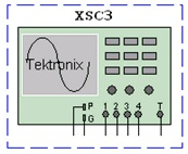
Figure 4.15.
Tektronix Oscilloscope Schematic Diagram
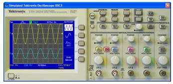
Figure 4.16.
Tektronix Oscilloscope Front Panel
Bode Plotter
The bode plotter displays the relative phase or magnitude response of an input and output signal. This is especially useful when characterizing the bandwidth of filter circuits.

Figure 4.17.
Function Generator Schematic Symbol
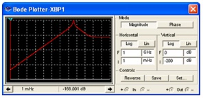
Figure 4.18.
Bode Plotter Front Panel
Spectrum Analyzer
The spectrum analyzer is used to measure amplitude versus frequency. This instrument is capable of measuring a signal's power and frequency components, and helps determine the existence of harmonics in the signal.
The spectrum analyzer displays its measurements in the frequency domain rather than the time domain. Usually the reference frame in signal analysis is time. In that case, an oscilloscope is used to show the instantaneous value as a function of time. Sometimes a sine waveform is expected but the signal, rather than being a pure sinusoidal, has a harmonic on it. As a result, it is not possible to measure the waveform's level. If the same signal is displayed on a spectrum analyzer, its amplitude is displayed, along with its frequency components, that is, its fundamental frequency and any harmonics it may contain.
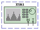
Figure 4.19.
Spectrum Analyzer Schematic Symbol
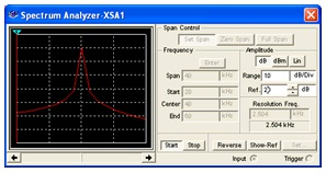
Figure 4.20.
Spectrum Analyzer Front Panel


