2.3. Electrical and Electronic Component Manipulation
in National Instruments Multisim*
Component Placement, Rotation, Selection and Wiring
Placement, Rotation, and Selection
Once parts have been selected from their respective database, it is time to place them onto the schematic, and wire them together. Double-clicking on a component in the browser will attach that component to the cursor. This behavior is known as “ghosting”. Ghosting helps guide users when placing components anywhere on the schematic by left-clicking at the desired location.
Components can also be rotated while ghosting, and any time after placement. To rotate a part while ghosting, press Ctrl-R. Ctrl-R will also work when a placed component is selected. Placed components can also be rotated by right-clicking on them and selecting 90 Clockwise or 90 CounterCW.
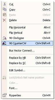
Figure 2.11.
Component Rotation
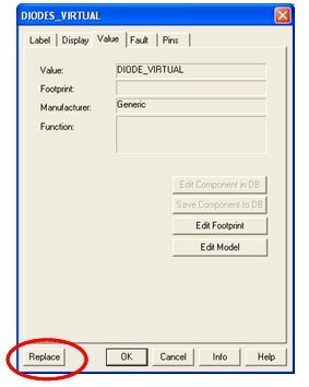
Figure 2.12.
Replacing Components
To select a component, simply-left click on it. To select multiple components, click and drag to create a selection around the desired components. A dashed line indicates that a component is selected. Individual elements of a symbol can also be selected, such as the component value and reference designator. To select these, left-click on the desired text or graphic element.
Holding the Shift key while selecting allows multiple components to be selected or de-selected.
Components can be replaced by right-clicking on them then selecting Replace Component(s) from the right-click menu. Users can then select the replacement components from the newly opened component browser. Multisim will connect the new component to the same nets as the original component.
Wiring
Multisim provides modeless operation — the action performed by the mouse cursor is dependent on the cursor’s location. There is no need to select a tool, or mode when working with Multisim.
The cursor will change depending on what object is underneath it. describes the different icons that the mouse cursor will display.
When the cursor is over a pin or terminal of a component, that component can easily be wired by left-clicking. When the cursor is over an existing wire and near a pin or terminal the net can easily be re-wired.
Left-click on the terminal to begin wiring, and to finish the wire, left-click on the destination terminal.
When a wire is placed, Multisim will automatically assign it a net number. Net numbers increase sequentially, beginning with 1. Ground nets are always numbered 0 — a requirement of the underlying SPICE simulator. To change a net number, or assign it a logical name instead, simply double-click on the wire.
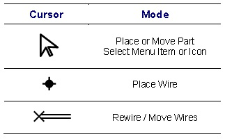
Figure 2.13.
Modeless Mouse Cursors
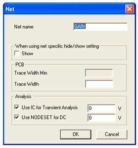
Figure 2.14.
Naming Nets
Autowiring by Touching Pins
Multisim also allows auto-connection of pins to wires, and pins to pins. To automatically connect a component to existing nets or pins, simply place that component so that its pins are touching an existing net or pin.
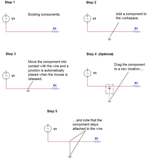
Figure 2.15.
Autowiring by Touching Pins
Autoconnect Passives
Multisim provides the ability to place a component in-line with an existing wire or set of wires.
To automatically split an existing wire around a component, simply place that component in-line with the wire (Figure 6).
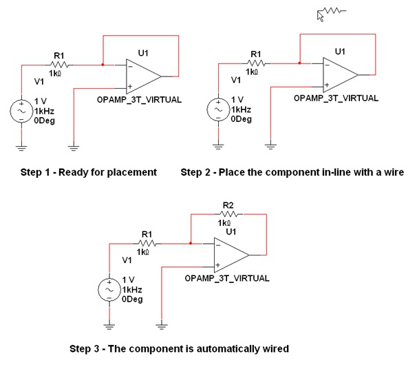
Figure 2.16.
Autoconnect Passives