System Analytics
Agents: system analysts, business analysts, scientists, engineers of renewable technology, electrical and electronics technology forum;
Objects : sustainable smart cities, smart villages;
Moves : requirements engineering, system design, prototype testing, erection, installation, testing, commissioning
System intelligence : Innovate a set of emerging technologies related to solar power;
 Photonic cell : Nano PV;
Power electronics : DC-DC boost converter, Inverter;
Topology : solar microgrid, standalone system, hybrid system;
Energy efficient load : LED light;
Battery storage;
Prof. Bruno Platini is giving a presentation on the emerging technology of solar power system; the key areas of his presentation are topology, photonic or solar cell, power elelctronics, energy storage system and load. The design of solar power system should be smart, compact, cost-effective, reliable, robust, modular, standardized and flexible in terms of service maintenance and focused on high performance and efficiency. There are lot of scopes of improvement of the existing design of solar water heaters, pumps, lighting systems, cookers and other home appliances in terms of appearance, size, quality, cost and product performance. The customers are very much conscious about product performance, quality of service, cost and values of a standalone solar power system. It is an interesting option to obtain system intelligence through value engineering and value analysis, brainstorming, standardization of product design, excellent quality control practice and efficient supply chain management.
Topology: One of the critical factors of system intelligence is topology of solar power system. There are different types of topologies such as standalone system, smart micro grid and hybrid system. Solar power is the modern trend of sustainable energy which requires flexible use of standalone, grid connected and hybrid system. The standalone systems are available in the form of innovative solar power enabled home appliance products such as solar cooker, lighting system, water pump, water heater and charger of computing devices. The basic components of a standalone rooftop system are solar or photovoltaic (PV) panel, inverter (optional for AC load), meter, protection relays and load. Smart Microgrids are intelligent electricity distribution networks that interconnect loads, distributed energy resources and energy storage systems within transparently defined electrical boundaries to act as a single controllable entity that can be grid connected or isolated. The system intelligence of a microgrid is associated with right sensing, communication, measurement and control technologies for effective generation and distribution of energy, self healing, stability analysis, fault analysis and load balancing mechanisms. Microgrid is an interesting and smart option of rural electrification. A hybrid system uses solar rooftop system and electrical grid alternatively according to the availability of power. There are issues of proper system integration, stability and load balancing with hybrid power system. It is logical to build an optimal number of solar thermal power plants and solar parks with medium and large capacities. But, standalone systems are also required in remote zones such as rural, forests, hilly and desert areas.
Photonic or Solar Cell : It is interesting to explore the dominant design of solar power system in terms of Nanotechnology based solar cells and solar power electronics. The system intelligence greatly depends on the innovation of smart materials and progress of mono and polycrystalline thin film photovoltaic technologies based on Si, semiconductors and nano PV. The efficiencies of Si and Ga As monocrystalline solar cell are relatively high. Thin film PV can reduce the cost of solar cells. CdTe and Cu (In,Ga)Se2 thin-film solar cells have efficiencies of 21% and 20.5% respectively. The production cost of CdTe thin-film modules is about $0.76 per peak watt; the same of mono and polycrystalline wafer Si solar is around $1.50 per peak watt (in 2011). Silicon solar cells can be classified into crystalline and thin film cells. The maximum efficiency of a crystalline solar cell is around 25.6%; the thickness may be as high as 400 µm. Reduced reflection loss, better light trapping and improved contact area result better efficiency of crystalline solar cells. Thin film silicon solar cells have reduced thickness of 50 µm; thin films can be deposited on low cost base and the efficiency may vary between 10.5 % and 21.2% . It is required to do similar type of analysis based on real up-to-date data.
The improved optical, chemical and electrical properties of nanomaterials can increase the efficiency of solar cells. Crystalline semiconductor III–V materials, polymeric materials, and carbon based nanostructures are used for third generation PV cells. Third generation PVs are based on nanostructure which can improve the efficiency of solar cells at relatively low cost. Quantum wells and quantum dots are used in crystalline solar cells to achieve high efficiencies. Quantum dots are nanometer sized crystallite semiconductors. These are artificial atoms improving the energy of the carriers. Nanocrystals increase the surface area of a solar cell and absorb more solar energy. The other options are rectifying antennas using wave property of light and organic solar cells. It is really challenging to improve the efficiency of solar cells and reduce the cost of production through various strategic moves such as carrier multiplication, multi-junction cell structure, hot electron extraction, impurity and intermediate band devices. The carrier multiplication strategy increases the photocurrent generated by a solar cell and improves energy conversion efficiency by creating additional electron-hole pairs in PV devices. A multi-junction structure captures a large fraction of solar spectrum while minimizing thermal losses by stacking cells in the order of band gaps; its efficiency is 37.9%. It is essential to improve the efficiency of the solar cells through innovation of smart materials and explore economical manufacturing technology. A smart analytics needs up-to-date data on efficiency and cost of different types of solar cells.
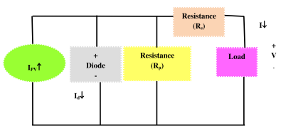
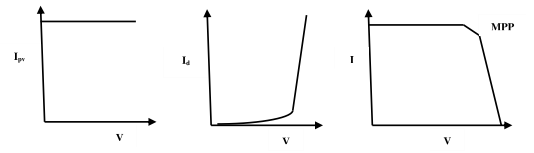
Figure 6.2 :Circuit of PV cell and Electrical Characteristics (I-V curve and MPP)
A Photovoltaic (PV) system converts sunlight into electricity directly. The basic building block of a PV system is PV cell; a set of PV cells are grouped to form panels or arrays. The cells are connected in series to obtain large output voltage. It is possible to obtain large output current by increasing the surface area of the cells or by connecting cells in parallel. A PV cell is basically a semiconductor diode with its p–n junction exposed to sunlight. The rate of generation of electrical carriers depends on the flux of incident sunlight and the capacity of absorption of the semiconductor. The capacity of absorption depends on the temperature, semiconductor band gap, reflectance of cell surface, intrinsic concentration of carriers of the semiconductor, electronic mobility and recombination rate Figure 6.2 shows the equivalent circuit of a PV cell. The basic equation describes the current (I) – voltage (V) characteristic of the ideal PV cell is I = Ipv – I0 [exp(qV/akT) – 1] where Ipv - current generated by the sun light , I - Shockley diode equation; I0 - reverse saturation or leakage current of the diode, q - electron charge (1.60217646 × 10⁻¹⁹ C), k - Boltzmann constant (1.3806503 × 10⁻²³ J/K), T (in Kelvin) - temperature of the p–n junction and a - diode ideality constant. A solar panel can generate its maximum voltage in full sunlight with no load; it is open circuit voltage of the panel. As the load of the solar panel increases, the output voltage decreases nonlinearly. The power output of a PV system depends on various factors such as module temperature, dirt and dust and DC to AC conversion. The output power of a PV system reduces as the module temperature increases. Dirt and dust on the solar module surface blocks some of the sunlight and reduces output (e.g. 7%). Some power is lost through DC to AC conversion in inverters (e.g. 10- 12%).
Nano technology for solar cells : The basic objective of Nanotechnology is to reduce the cost per solar cell and improve the energy conversion efficiency. The emerging technology is looking for efficient solar cells at reduced cost which can change the economics of energy market. The scope of nanotechnology may be explored in terms of nanoparticles, nanotubes, nanowhiskers as antireflective coating, multi- junction solar cells (MJSC), dye sensitized solar cells (DSSC) and quantum dot solar cells (CdSe QD). The technology of solar cells has been evolving through three generations : first generation having crystal silicon cells dominating the market, second generation having amorphous silicon thin film cells at reduced cost and third generation adopting nanotechnology with a mix of flexible and printable substrates and electronically conducting nanomaterials.
The structure of nanoparticles determines what range of frequencies they can resonate at or accept plasmon energy levels : roughly 575 - 9000 nm or 2.25 - 0 eV for nanoshells, 475 - 1400 nm or 2.6 - 1.0 eV and 600 -1200 nm or 2.2 - 1.25 eV for nanocubes. In dye-sensitized solar cells, electrons pass through a TiO2 layer and gather on fluorine-doped SnO2 of a glass surface. In CdSe QD system, the split and transfer process occurs between a polymer and CdSe dots, which provide tunnels to the electrodes. TiO2 only collects 5% of the solar spectrum with a bandgap of 3.2 eV. TiO2 can be doped with N. Antireflection (AR) coating and quantum wells can also improve the energy conversion efficiency. Multi-junction cell allows the absorption of larger range of wavelengths in the solar spectrum through stacking of solar cells of different band gaps in series. A 3-junction solar cell can have about 40.7% efficiency under 240-sun illumination.
Power Electronics: The next interesting issue is power electronics. Prof. Platini is trying to focus on DC-DC Boost converter, microinverter and maximum powerpont tracking algorithm.
DC-DC Boost Converters : A DC chopper can be used as a DC converter to step up or step down a fixed dc voltage. The chopper can also be used for switching mode voltage regulators and for transferring energy between two dc sources. But, harmonics are generated at the input and load side of chopper and the harmonic can be reduced by input and output filter. A chopper can operate on either fixed or variable frequency. A simple step-up boost converter is comprised of dc input voltage source VS, boost inductor L, controlled switch S, diode D, filter capacitor C and load resistance R [Figure 6.3, 6.4] . When S is on, the current in the boost inductor increases linearly. The diode D is off at the time. When S is turned off, the energy stored in the inductor is released through diode to RC circuit. The switch is operated with a duty ratio  = ton / (ton + toff ) = ton / T; T= 1/f, f : switching frequency; The average value of the output voltage is VO = .VS .VS..T = (VO − VS)(1 − )T ; DC voltage transfer function MV = VO/VS = 1/ (1-); the output voltage is always greater than the input voltage. The boundary value of inductance : Lb = (1 − )2R; Cmin = .VO/(VrR.f); a large filter capacitor is required to limit the output voltage ripple.
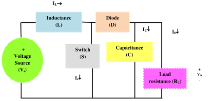
Figure 6.3 : DC boost converter – simple circuit
Let us perform the strength and weakness analysis of a DC-DC boost converter. Solar panels convert sun irradiation into electrical energy using photovoltaic effect. The output voltage of a solar panel varies based on solar irradiation and temperature; it is not possible to connect sophisticated electrical and electronic load with PV panels for this reason. So, the circuit requires a reliable and efficient DC- DC boost converter with constant step-up voltage. Here, the critical success factors are converter configuration, control mechanism, integration with power utilities, output limitation, efficiency, sensors and complex control algorithm. The cost of converter is approximately 15% of the system cost. But, there are various constraints such as reduction in gain, decreased output voltage, complex control schema, less efficiency and increased cost, variable PV power irradiation and load.
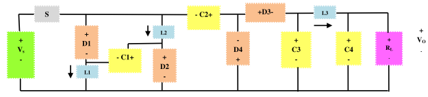
Figure 6.4 : DC-DC boost converter – complex circuit
The possible solution may be high output voltage DC-DC boost converter with MPPT algorithm based on PI controller. A PV module with parallel connection of a set of panels can obtain high current. For a PV panel, power capacity is about 100- 300W, MPPT Voltage range is 15-40V, DC-DC boost converter is used for step up conversion of low voltage of a PV panel. The circuit a DC-DC boost converter consists of static switch, diodes, capacitors, inductors and load resistance. The important design parameters are input voltage, inductance, capacitance, load resistance, duty ratio, switching frequency. The other variables are supply voltage load voltage, supply current and load current.
Maximum Power Point Tracking [MPPT] : What are the strategic options to obtain maximum available solar power from PV panels?
 DC-DC boost converter with high gain may be connected with an inverter;
Series / parallel connection of arrays of solar panel;
Maximum power point tracking algorithm (MPPT) based on PI control;
The power output of solar systems increases with the use of efficient sun tracking methods such as polar axis and azimuth / elevation types. AI based solar tracking policy may consider various factors such as forecasted weather conditions, energy consumption and complex closed-loop PI control logic.
Power Amplifier: The system intelligence of a solar power system is highly correlated to the design and topology of power electronic circuit. The energy conversion efficiency of a photonic solar cell is low (e.g. 20%). Therefore, a solar power system needs the support of a power amplifier. It is a new concept. Let the input power of a power amplifier is p; the output of the amplifier should be P = k.p where k is a constant greater than 1. Recently, Mitsubishi Electric Corporation has developed a prototype gallium nitride high electron mobility transistor amplifier with 100W output power for satellite communications. Generally, voltage and current amplifiers are used in boost converter. A voltage amplifier can raise the voltage generated by solar panels in poor light condition.
Is DC-DC boost converter considered as equivalent to power amplifier? What is boosted V or I? P=VI; If I  and V = constant then P; If V , I ; then P ; but increased I results overheating of electrical and electronic devices. P= Constant; if V then I
 . If V and I = constant then P; in case of PV power generation with voltage operation mode, high output voltage DC-DC boost converter maximizes the output of PV panel. Let us consider circuit intelligence of maximum power point tracking schema.
The solar power system requires the support of an intelligent load manager for effective monitoring of voltage (V), frequency (f), current (I), power (P), energy (E) and maximum power point tracking (MPPT). Maximum Power Point Tracking (MPPT) techniques find the voltage VMPP or current IMPP automatically at which a PV cell should operate to obtain maximum power output PMPP under a given temperature and irradiance. There are different MPPT techniques such as hill climbing, Kalman filtering and perturb and observe (P&O) methods. Hill climbing is related to a perturbation in the duty ratio of the power converter and P&O involves perturbation in the operating voltage of the solar cell. There are differences among various MPPT techniques in terms of complexity, number of sensors, convergence speed, cost, effectiveness, implementation hardware and use of soft computing based microcontrollers (e.g. Fuzzy Logic, Artificial Neural Network).
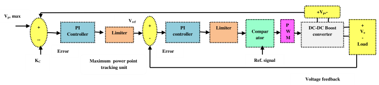
Figure 6.5 : MPPT Control Circuit
Voltage control mode is considered to maximize power generation by PV panel. For example, MPPT may be set at 10V to attain maximum power 500W. The circuit for MPPT consists of two voltage sensor feedback, two P-I controllers, two limiters and a signal compensator. The feedback voltage from PV panel is compared with maximum reference voltage and obtained error is regulated through a P-I controller to obtain the output reference voltage. It is the maximum fixed output voltage reference for the converter. The feedback from DC load voltage is compared with the reference voltage to obtain the error which is then applied to another P-I controller to compensate the error. The signal of P-I controller defines the duty ratio for PWM mode. is then compared with a ramp-signal to generate pulses for static switch of the converter circuit. The proportional and integral gain of PI controller are fine-tuned to maintain MPPT under variable irradiation and load.
Solar micro-inverter : Inverters convert from DC to AC while rectifiers convert from AC to DC. Many inverters are bi-directional; operate in both inverting and rectifying modes. A standalone PV system operates at 110/240V AC with 50/60 Hz frequency. Inverters operate at 12, 24, 48, 96, 120 or 240V. An inverter for a stand- alone PV system should have sinusoidal output voltage, voltage and frequency within allowable tolerance limits, good voltage regulation and high efficiency at light loads. Inverters use semiconductor devices such as metal oxide semiconductor field effect transistor (MOSFET) and insulated gate bipolar transistors (IGBT). These devices are used in units up to 5 KVA and 96V DC. They have the advantage of low switching losses at higher frequencies. Voltage Source Inverters (VSI) and Current Source Inverters (CSI) are usually used in standalone PV applications. They can be single phase or three phase and use square wave, quasi-square wave, and pulse width modulation techniques.
The topologies, control method (e.g. pulse width modulation [PWM], boundary conduction mode [BCM], discontinuous conduction mode [DCM]) and soft switching methodologies using MOSFETs and IGBTs are the basic elements of circuit intelligence in power electronic inverters and converters. A PV ac module is called microinverter which has benefits in terms of maximum power point tracking efficiency, low manufacturing cost, safe and simple installation procedure. Module integrated converters or microinverters (MICs) are designed to interface a single, low-voltage (e.g. 25–40 V) panel to the ac grid. Such converters provide benefits in terms of ease of installation, system redundancy, and increased energy capture in partially shaded conditions. An energy storage block can be used in a series connected path with the line interface block providing independent control over the capacitor voltage, soft-switching devices and full four quadrant operation with the grid. Several factors must be considered while selecting or designing an intelligent inverter for solar power system such as power conversion efficiency, electrical losses, rated power, duty rating, input voltage, voltage regulation, voltage and current protection, frequency and power factor.
A solar micro-inverter converts DC from a single solar panel to AC. The combined output from several microinverters is fed to the electrical grid. Solar panels produce DC voltage that depends on module design and lighting conditions. For example, panels using 6-inch 60 cells can produce a nominal 30 volts. The panels are connected in series to produce 300 - 600 V DC. The inverter converts this DC voltage into 110V / 230VAC, 50 Hz; microinverters are typically rated between 190 and 220 W and can tune the output of PV panel. Microinverters contrast with conventional string inverters having advantages simplicity in system design, space utilization, cooling and safety. Even small amount of shading, debris or snow lines on any one solar panel or a complete panel failure do not reduce the output of the entire array disproportionately. Each microinverter harvests optimum power through maximum power point tracking. The efficiency of a panel's output is strongly affected by the load. Inverters use MPPT to ensure optimal energy harvest by adjusting the applied load. Microinverters may not need large transformers; large electrolytic capacitors can be replaced by thin-film capacitors.
Module integrated converters or microinverters (MICs) can be used for single-phase grid-tied photovoltaic applications with a topology that places the energy storage block in a series-connected path with the line interface block. It can interface a single low voltage 25-40V PV panel to an AC grid. This design provides various types of benefits such as soft-switching for all semiconductor devices, independent control over capacitor voltage and full four-quadrant operation with the grid, ease of installation, system redundancy, and increased energy capture in partially shaded conditions. A third-port topology places energy storage buffer block in series with the line voltage interface. The topology achieves high efficiencies with its continuous constant power operation.
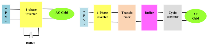
Figure 6.6 : Microinverter topology
The circuit consists of four functional blocks of the converter: (1) high-frequency resonant inverter, (2) transformation stage, (3) energy buffer and (4) cycloconverter. Each is connected in series, with a common high frequency resonant current linking them together. This topology allows bidirectional power flow in each block and it is possible to reduce heavy conduction loss through soft switching techniques. Typical rating of a microinverter is 100W,32V input, 240V output, 95% efficiency. In the classification of inverter topology, the location and the operation of energy storage buffer within the converter are two important parameters. Single stage topologies (e.g. flyback, ac-link) place capacitance in parallel with PV panel. The second option is two complete cascaded conversion stages with energy storage at an intermediate dc bus. Generally electrolytic capacitors are used for dc energy storage due to high energy density, but suffer from long-term failure rates.
Photovoltaic Grid-Tied-Interleaved Flyback Microinverters can achieve high efficiency in wide load range by intelligent control strategies such as Boundary conduction mode (BCM) and discontinuous conduction mode (DCM) [Table 6.1]. In this case loss analysis plays a critical role in estimation of efficiency of flyback microinverters. The dominant losses at heavy load include conduction loss of the power MOSFETs, diodes and transformer; the dominant losses at light load include gate driving loss, turn-off loss of power MOSFETs and transformer core loss.
Energy Storage System: The output of solar photovoltaic system varies significantly depending on the time of a day, weather and shading conditions. The system requires a stable energy source and it should be dispatched at request. It demands an efficient energy storage system for solar power system in the form of batteries. There are different options for integrating an energy storage system into a solar PV system such as PV to grid (dc to ac), PV to battery (dc to dc), battery to grid (dc to ac), and battery/PV to grid (dc to ac). An intelligent converter can be used for both single phase and three phase PV battery application. The system is expected to have improved efficiency, reduced weight, volume and cost and minimum number of conversion stages. Li-ion battery can be used for solar energy storage system. It requires a constant current constant voltage charging algorithm. The battery should be charged at a set current level until it reaches its final voltage.
Load : The system intelligence is associated with energy efficient