reflection Sij, the perpendicular to mirror and the vertical axis of SA - takes their common
plane, perpendicular to plane XOY while SA is rotating, an optical signal, having travelled a
path ”Sij - mirror M - objective O - optical channel OC - photoreceiver PR ”. It makes an
electrical stop signal. A start signal is previously formed by SA by means of a zero-sensor
(installed on a bar b axis) (Rivas et al., 2008).
a)
b)
Fig. 10. a) Triangulation scheme, b) Dynamic triangulation scanner
The principle of this system is promising, although it has multiples disadvantages when the
system is actually developed and running. The usage of the timing belts for the angular
rotation of the system is one of them. Moreover, the system must undergo a thoroughly
calibration to guarantee that the mirror rotates parallel to the system, and the receptor motor
is not sufficient to guarantee constant rotational speed. Lastly, there are some components
that vibrate and generate unwanted noise.
4.2.4 3D Rotational Body Scanner
The Rotational Body Scanner uses the principals of Dynamic Triangulation Scanner. (Basaca
& Rodriguez, 2010). Increases its precision, decreases the mechanic noise sources and makes
the addition of a stationary rotation system independent of timing belts (Rivas et al.,2008).
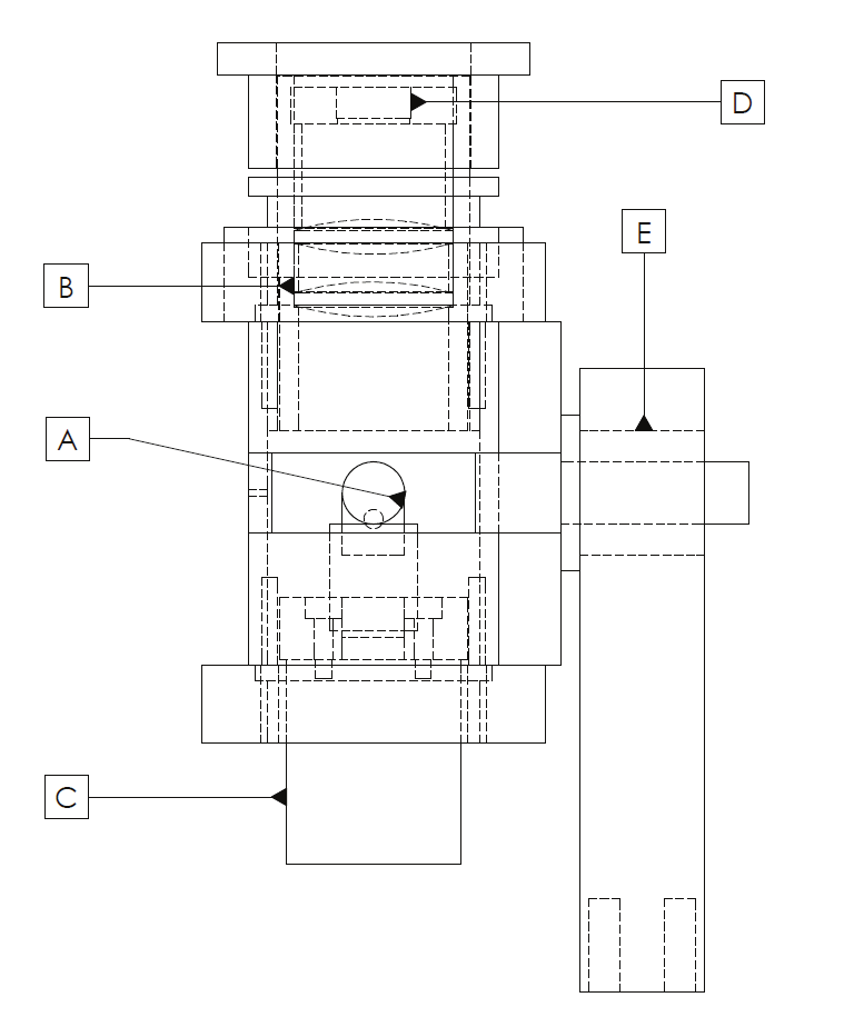
The system receptor (see Figure 11) consist of 5 main components A) 45 degree rotational
mirror, whose principal function is to direct the laser light beam towards the lenses (targets).
B) Targets, whose function is to concentrate the light beam onto photodetector. C) DC
Motor, which rotates the mirror. D) Photodetector, it captures the light beam located within
the frequency range of the laser. E) Flat Bearing, allows the rotation in the angular axis of the
system.
318
Optoelectronic Devices and Properties
Fig. 11. System receptor
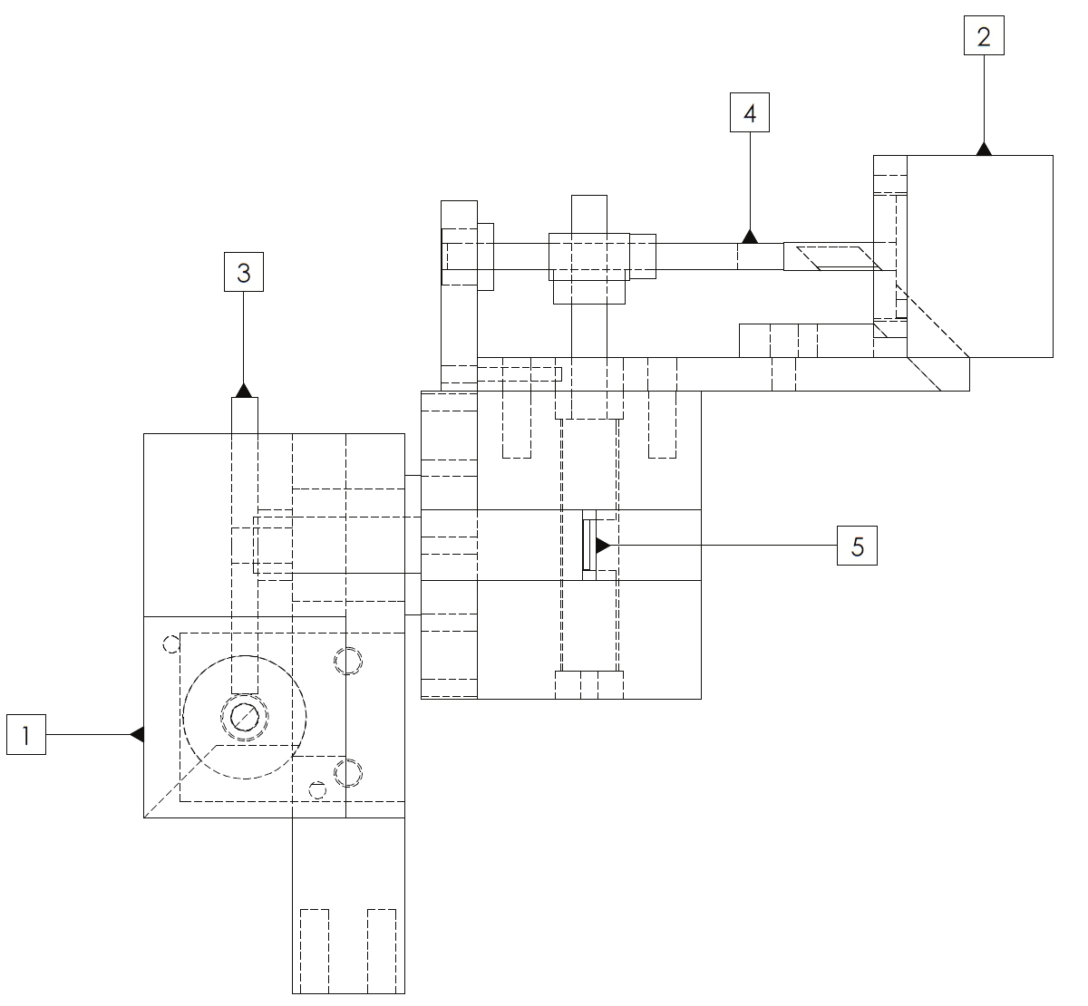
The system projector has 5 main components (see figure 12), which are the following: 1)
Step Motor of angular rotation, whose main function is to control the rotation of the entire
system. 2) Step motor for the mirror rotation, which controls the mirror rotation. 3) System’s
rotation gear, increases the precision of the system since it gives a 10:1 ratio gear-motor. 4)
Mirror’s rotation gear increases the precision of the system giving a 10:1 ratio gear. 5)
Mirror, reflects the laser light beam towards the scanning body.
Fig. 12. System projector
The laser light projector emits the light at different angles towards the body. And at the
same time the receptor rotates until it detects the light deflected by the body. When the
mirror of the receptor deflects the scattered light towards the target and concentrates the
light towards the photodetector, an electronic pulse is emitted which indicates the point has
been detected. A relationship between the rotation time and detection time shows the angle
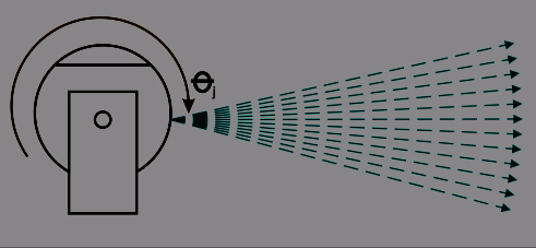
3D Body & Medical Scanners’ Technologies: Methodology and Spatial Discriminations
319
in which the receptor detects the point. Since the projector rotation is controlled by the user,
the angle of the projector is known at all times. The relationship between the 2 angles and
the known distance between the projector and receptor gives each of the captured
coordinates.
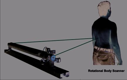
Fig. 13. 3D Rotational Body Scanner
As shown in figure 13, the projector and receptor are separated by a bar that gives the exact
distance of 1 meter between them, and located in the bar is the laser light source. Within the
bar the laser also gets aligned and locked avoiding measurement errors. The triangulation
principle used is well known, and some of the advantages given by this system is the
angular rotational mechanism (see figure 13) which allows the rotation with no chains, an
increment in resolution of 10 times by using gears that gives 1 rotation for each 10 rotations
that gives the step motor, inaccuracy caused by friction are decreased by using
polytetraflourtethylene flat bearings which has the lowest friction coefficient of all materials,
and the fabrication cost is economic.
4.3 Traceable 3D laser imaging metrology
The statement of uncertainty is based on comparisons with standards traceable to the
national units (SI units) as requested by ISO 9000-9004. For example, manufacturers of
theodolites and CMM manufacturers use specific standards to assess their measuring
instruments. A guideline called VDI/VDE 2634 has been prepared in Germany for close
range optical 3D vision systems. It contains acceptance testing and monitoring procedures
useful for practical purposes for evaluating the accuracy of optical 3D measuring systems
based on area scanning – bundle of rays. These systems work according to the principle of
triangulation, e.g. fringe projection, Moiré techniques and photogrammetric/scanning
systems based on area scanning (Beraldin et al., 2007). According to National Institute of
Standards and Technology (NIST) in the Proceedings of the LADAR Calibration Facility
Workshop, Gaithersburg, June 12 – 13, 2003 the steps to perform a 3D laser scanning
calibration could be the following.
Calibration of the direction component: Using theodolite–type scanners, the direction
affecting instrumental errors of the laser-scanner could be calibrated by procedures known
from theodolites These are:
1. Vertical axis wobble, which acts as a lever effect, if the scanner does not correct this
influence by inclination sensors.
2. Eccentricity of scan center.
3. Collimation axis error.
4. Horizontal axis error.
320
Optoelectronic Devices and Properties
However no internationally recognized standard or certification method exists; the
evaluation of the accuracy, resolution, repeatability or measurement uncertainty of a 3D
imaging system still remains the responsibility of the user.
5. Conclusions
Not all scanning methods are as accurate as the diverse applications demands. None of the
systems is superior in every area of applications.
The MillimeterWave based systems are sufficient for object detection but underdeveloped to
be used in the medical environment where accuracy is needed. The main disadvantage of
these systems is that their accuracy and contrast are sacrificed to be able to perform real time
scanning.
The diverse techniques used in Photogrammety are appropriate to perform the modeling
representation of the scanned objects, although not all techniques have the capability to
perform measurements, such as the White Light Scanner by 3D3 Solutions mentioned above.
This is one of the main reasons why the laser scanner based systems are preferred when
measurements and surface areas are needed to be known, due to their attributes such as
accuracy and efficiency.
If one of the system requirements to be met is that the 3D Model can be digitally rotated to
offer its view in different angles, multiple laser scanner based systems can be used
simultaneously. The speed of the laser scanning will be proportional to the number of
systems used, since the simultaneously measurements of the multiple systems do not
interfere between them. This laser scanning system attribute differs with the
Photogrammetry based systems since they cannot perform the scan operation
simultaneously due to the light projections interference, such as Formetric 3D/4D, which
makes the speed ratio inversely proportional.
The 3D Rotational Body Scanner increases by 10 times its resolution in comparison with the
former 3D Triangulation method. This is possible by using gears that gives 1 rotation per
each 10 that gives the step motor. The increase in accuracy given by this improved method
can be potentially used in other applications, for example, the scan of small parts of the
human body, such as fingers and teeth.
Moreover, the 3D Rotational Body Scanner decreases significantly the mechanical sources of
noise, and guarantee less calibration since is a more stable than the former 3D Dynamic
Triangulation scanner.
The combination of the photogrammetry method and the 3D dynamic triangulation method
could be an interesting area of opportunity. The image modeling phase could be obtained
through the photogrammetry techniques and the accuracy and dimensional measurements
could be complemented by the improved 3D Rotational Body Scanner system, although this
is yet to be explored.
6. References
Azernikov, S.; Fischer, A. (2008). Emerging non-contact 3D measurement technologies for
shape retrieval and processing, Virtual and Physical Prototyping, Vol. 3, No. 2 (June
2008) pp 85-91, ISSN: 1745-2759.
Básaca, Luis C.; Rodríguez, Julio C.; Sergiyenko, Oleg;. Tyrsa, Vera V; Hernández, Wilmar;.
Nieto Hipólito, Juan I; Starostenko, Oleg. 3D Laser Scanning Vision System for
3D Body & Medical Scanners’ Technologies: Methodology and Spatial Discriminations
321
Autonomous Robot Navigation, Proceedings of IEEE (ISIE-2010), Bari, Italy, July 4-7,
2010, pp.1773-1779, ISBN 978-1-4244-6390-9.
Beraldin, J.A.; Rioux, M.; Cournoyer, L.; Blais, F.; Picard, M.; Pekelsky, J (2007). Traceable 3D
Imaging Metrology, Proc. SPIE 6491, ISBN: 9780819466044, California, USA,
January 2007, SPIE, San Jose.
Beraldin, J.A. (2004) Integration of Laser Scanning and Close-range Photogrammetry the
Last Decade and Beyond, ISPRS Journal of Photogrammetry and Remote Sensing,
Volume XXXV, No. B5 (July 2004) pp. 972-983, ISSN: 1682-1750.
Bjarnason, J. E.; Chan, T. L. J.; Lee, A. W. M.; Celis, M. A.; Brown, E. R. (2004) Millimeter-
wave, terahertz, and mid-infrared transmission through common clothing, Applied
Physics Letters, Vol. 85, No. 4, (June 2004) pp. 519 -521, ISSN: 0003-6951.
Boehnen, C.; Flynn, P. (2005) Accuracy of 3D Scanning Technologies in a Face Scanning
Scenario, Proceedings of 3-D Digital Imaging and Modelling, pp 310-317, ISBN: 0-7695-
2327-7, Ontario Canada, June 2005, IEEE, Ottawa.
Calva, D.; Calva, S.; Landa, A.; Rudolph, H.; Lehman1, M. (2009). Face recognition system
using fringe projection and moiré: characterization with fractal parameters, IJCSNS,
Vol.9, No.7, (July 2009) pp 78 – 84, ISSN: 1738-7906.
Creath, K.; Wyant, J. C. (1992). Moiré and Fringe Projection Techniques , Optical Shop Testing,
Editor: Daniel Malacara pp. 653 – 685, John Wiley & Sons, ISBN: 0-471-52232-5,
New York.
Di, W.; Naiguang, L (2008). A pre-processing method for the fringe image in phase
measuring profilometry, Proc. SPIE, Vol. 6623, No. 66231A, (March 2008) pp 1 – 8,
ISSN: 0277-786X.
Emmanuel P. Baltsavias (1999). A comparison between photogrammetry and laser
scanning. ISPRS Journal of Photogrammetry and Remote Sensing, Vol. 54, No. 2-3,
(March 1999) pp. 83 – 94, ISSN: 0924-2716.
Haworth, C.D.; De Saint-Pern, Y.; Clark, D.; Trucco, E.; Petillot, Y.R. (2006). Detection and
Tracking of Multiple Metallic Objects in Millimetre-Wave Images, International
Journal of Computer Vision, Vol. 71, No. 2, (June 2006) pp 183-196, ISSN: 0920-5691
Hierholzer, E. Drerup, B. (1995). High-resolution rasterstereography. Three-Dimensional
Analysis of Spinal Deformities, Editors: Amico, D’ M. Merolli, A. Santambrogio, G.C.
pp. 435 – 439, The Netherlands: IOS Press, ISBN: 90-5199-181-9, Amsterdam.
Howald, R.L.; Clark, G.; Hubert, J. Ammar, D. (2007), Millimeter Waves: The Evolving
Scene, Technologies for Homeland Security IEEE Conference on HST, pp.234-239, ISBN:
1-4244-1053-5, Massachusetts USA, June 2007, IEEE, Woburn.
Leifer, J. (2003) A close-range photogrammetry laboratory activity for mechanical
engineering undergraduates, Frontiers in Education, 2003. FIE 2003. 33rd Annual, Vol
2, No F2E, (November 2003) pp 7 – 12, ISSN: 0190-5848.
Lerch, T.; MacGillivary, M.; Domina, T. (2007). 3D Laser Scanning: A Model of
multidisciplinary research, Journal of Textil and Apparel, Technology and Management,
Vol. 5, No. 4 (October 2007) pp 1-21, ISSN: 1533-0915.
Lippold, C.; Danesh, G.; Hoppe, G.; Drerup, B.; Hackenberg, L. (2007). Trunk Inclination,
Pelvic Tilt and Pelvic Rotation in Relation to the Craniofacial Morphology in
Adults, Angle Orthodontist, Vol. 77, No 1, (January 2007) pp 29 – 35, ISSN: 0003-
3219.
322
Optoelectronic Devices and Properties
Liu, H.B.; Zhong, H.; Karpowicz, N.; Chen, Y. (2007) Terahertz Spectroscopy and Imaging
for Defence and Security Applications, Proceedings of the IEEE, Vol. 95, No. 8,
(October 2007) pp.1514-1527, ISSN: 0018-9219.
Rivas Lopez, M.; Sergiyenko, O. & Tyrsa, V. (2008). Machine vision: approaches and
limitations, In: Computer vision, Xiong Zhihui, (Ed.), pp. 395-428. Editorial: IN-
TECH, ISBN 978-953-7619-21-3, Vienna, Austria.
Rusinkiewicz, S.; Hall-Holt, O.; Levoy, M. (2002). Real-time 3D model acquisition. ACM
Transactions on Graphics (TOG), Vol. 21, No. 3, (July 2002) pp. 438 – 446, ISSN: 0730-
0301.
Sergiyenko, O.; Hernandez, W.; Tyrsa, V.; Devia Cruz, L.; Starostenko, O. & Pena-Cabrera,
M. (2009). Remote Sensor for Spatial Measurements by Using Optical Scanning,
Sensors, 9(7), July, 2009, MDPI, Basel, Switzerland, pp. 5477-5492. ISSN 1424-8220.
Treleaven, B.; Wells, J. (2007). 3D Body Scanning and Healthcare Applications. Computer,
Vol. 40, No. 7, (August 2007) pp. 28 – 34, ISSN : 0018-9162.
16
Research and Development of the Passive
Optoelectronic Rangefinder
Vladimir Cech1 and Jiri Jevicky2
1Oprox, a.s., Brno
2University of Defence, Brno
Czech Republic
1. Introduction
1.1 Basic specification of the problem
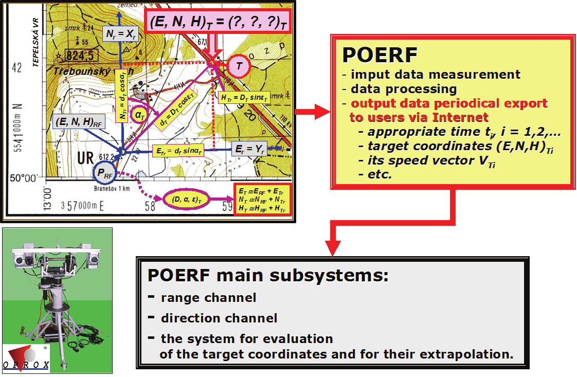
The topographical coordinates of an object of interest (the target), which is represented by
one contractual point T = ( E, N, H)T, need to be determined indirectly in many cases that
occur in practice, because an access to respectively the target and the target point T is
disabled due to miscellaneous reasons at a given time. Hereafter we will confine to methods
that make use of specialized technical equipment (rangefinders) to determine coordinates of
the target point T – Fig. 1.
The point P RF = ( E, N, H)RF represents a contractual position of the rangefinder in the
topographical coordinate system, D T is the target slant range measured by means of the
rangefinder. This value D T represents the estimate of the real slant range of the target D T0
that is equal contractually to the distance of points P RF and T. The angle ε T is the measured estimate of the elevation of the target ε T0 and the angle α T is the measured estimate of the
target azimuth α T0. The coordinates ( D, ε, α) are relative spherical coordinates towards the
contractual position of the rangefinder which is represented by the point P RF.
The rangefinder is a device that, from the view of Johnson’s criterion for optical systems
classification, functions to locate the target (target coordinates ( E, N, H)T) and usually it also
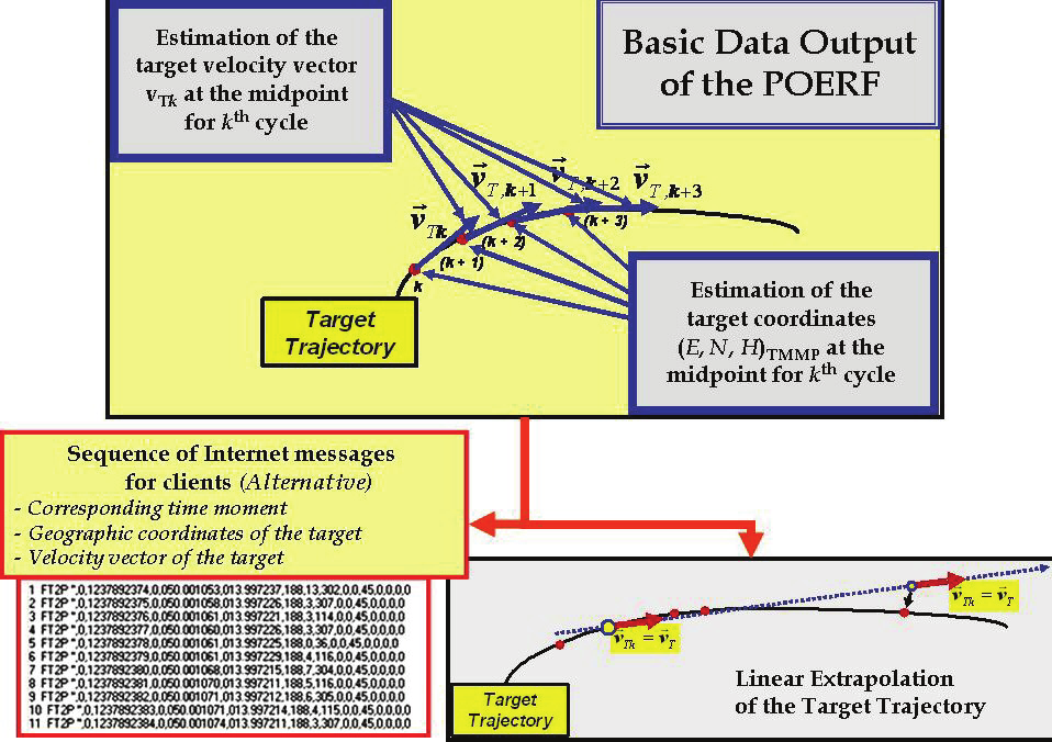
functions to determine motional parameters of the target that are primarily represented by
the instantaneous target velocity vector vT – Fig. 2.
Typical measured ranges interval for ground targets is from 200 to 4000 m and for aerial or
naval targets from 200 to 10000 m or more.
1.2 Passive optoelectronic rangefinder (POERF)
The passive optoelectronic rangefinder (POERF, Fig. 1, 8) is a measurement device as well as
a mechatronic system that measures geographic coordinates of objects (targets) selected by
an operator in real time (in online mode). In the case of a moving object, it also automatically
evaluates its velocity vector vT and simultaneously extrapolates its trajectory – Fig. 2.
Active rangefinders for measurement of longer distances of objects (targets), e.g. pulsed
laser rangefinders (LRF), emit radiant energy, which conflicts with hygienic restrictions in
many applications and sometimes with given radiant pollutions limitations, too. In security
and military applications there is a serious defect that the target can detect its irradiation.
The use of POERF eliminates mentioned defects in full.
324
Optoelectronic Devices and Properties
Fig. 1. Input/Output characteristics of POERF (the demonstration model 2009)
Fig. 2. Principle of measurement of the target trajectory and the data export to users (clients)
The POERF measurement principle is based on the evaluation of information from stereo-
pair images obtained by the sighting (master) camera and the metering (slave) one (see the
subsection 4.1 and the Figure 9). Their angles of view are relatively small and therefore a
spotting camera with zoom is placed alongside the sighting camera – Fig. 1, 9. This spotting
camera is exploited by an operator for targets spotting. After operator’s steering the cameras
towards a target, the shots from the sighting camera serve to evaluate angle measured errors
and to track the target automatically (see the section 3).
Research and Development of the Passive Optoelectronic Rangefinder
325
The POERF is able to work in two modes: online and offline (processing of images saved in
memory – e.g. on the hard disc). The offline mode enables to measure the distance of
fleeting targets groups in time lag to approx. 30 seconds. The active rangefinders are not
able to work in a similar mode (see the section 2).
In general, the POERF continues to measure the UTM coordinates (Fig. 1, 2) of moving
target with rate from 10 to 30 measurements per second and extrapolates its trajectory. All
required information is sent to external users (clients) via the Internet in near-real-time
whereas the communications protocol and the repetitive period (for example 1 s – Fig. 2) are
preconcerted. The coordinates can be transformed to the coordinate system WGS 84 and
sent to other systems – in accordance with the client’s requirement.
Presumed users of the future system POERF are the police, security agencies (ISS –
Integrated Security Systems, etc.) and armed forces (NATO NEC – the NATO Network
Enabled Capability, etc.).
1.3 The state of POERF research and development, used methods and tools, results
1.3.1 Demonstration model of the POERF
A demonstration model of the POERF (Fig.1, 8) was presented to the opponent committee of
the Ministry of Industry and Trade of the Czech Republic within the final opponent
proceeding in March 2009. The committee stated that POERF is fully functional and
recommended continuing in its further research and development. This chapter will give
basic information about the research and development of this POERF demonstration model.
The working range of measured distances is circa from 50 m to 1000 m at the demonstration
model (see the subsection 4.1).
1.3.2 Simulation programs Test POERF, Test POERF RAW and the Catalogue of
targets
In this chapter the basic possibilities of simulation program Test POERF (see the section 5)
are presented. This program serves to simulate functions of the range channel core of the
POERF. It allows verifying the quality of algorithms for a target slant range finding from
taken stereo pair images of the target and its surroundings. These images are generated as a
virtual reality by a special images generator in the program – Fig. 12.
Next, we present consequential simulation software package Test POERF RAW which
works with taken images of a real scene (see the section 5, too). The package presently
consists of three separate programs: the editing program RAWedi, the main simulation
program RAWdis and the viewer RAWpro. The editor RAWedi allows editing of stereo pair
images of individual targets and supports the creation of the Catalogue of targets. The
simulation program RAWdis serves for testing algorithms for estimation of horizontal
stereoscopic disparity (stereo correspondence algorithms) which are convenient for the use
in POERF. Simulation experiments can also help to solve problems in the development
process of the software for a future POERF prototype.
In publications that deal with problems of stereoscopic disparity determination there is
constantly emphasized the deficiency of quality stereoscopic pairs of varied object images,
which are indispensable to testing the functionality and quality of various algorithms under
real conditions. Considering the POERF specifics, we have decided to create own database
of horizontal stereo pair images of targets with accurately known geographic coordinates –
shortly the “Catalogue of Targets” (see the section 5 and the Figures 16, 17).
326
Optoelectronic Devices and Properties
The stationary “targets” (73 objects) were chosen, so that on the one hand they cover slant
ranges from c. 100 m to c. 4000 m and on the other hand their appearance and placement
should be convenient for unique determination of their stereoscopic disparity – Fig. 17. The
number of successive stereo pair images of every target is minimally 512, which is
precondition for statistical processing of simulation experiments results.
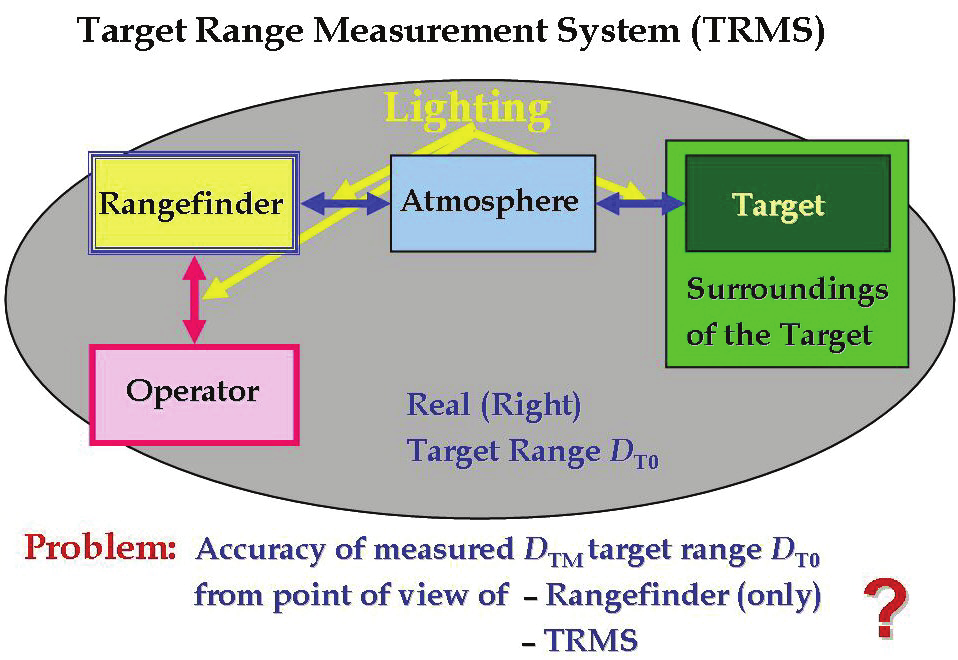
Fig. 3. Target Range Measurement System – TRMS
1.4 What has been done by other researchers
The principle of passive optoelectronic rangefinder has been known minimally since the 50’s
or 60's of the 20th century (see the subsection 3.1). The development was conditioned
primarily by progress in the areas of digital cameras and in miniature computers with
ability to work in field conditions (target temperature limit from –40 to +50 °C, dusty
environment, etc.) and to realize the image processing in the real-time (frame rate minimally
from 5 to 10 frames per second, ideally from 25 to 50 fps).
Our development started initially on a department of Military Academy in Brno (since 2004
University of Defence) in the year 2001 in cooperation with the firm OPROX, a.s., Brno. The
centre of the work was gradually transferred into OPROX that has practically been the
pivotal solver since 2006 (see the subsection 3.2).
The patents of POERF components have been published since the end of 1950’s but there are
no relevant publications dealing with the appropriate research and development results. We
have not found out that similar device development is being carried out somewhere else.
We have found only one agency information that a POERF was developed in Iran
(www.ariairan.com, date: 20.7.2008). The problem itself consists particularly in users’
unshakable faith in limitless possibilities of laser rangefinders and probably in the
industrial/trade/na