sin ]
( F ) and isotropic ( F ) forces.
av
is
Fig. 4. Force polygon and force capabilities.
In this work, six different scenarios of operational conditions in which the forces and
moments interact are presented. Table summarizes the six operational conditions which
lead to two force analyses and four moment analyses.
Operational Condition
Analysis
Prescribed Moment
Force Analysis:
Largest Allowable Force with an Associated
Find Range of Available and
Moment
Isotropic Forces
Prescribed Force (magnitude and direction)
Largest Allowable Moment with an Associated
Moment Analysis:
Force
Find Range of Moments
Prescribed Isotropic Force (magnitude)
Prescribed Available Force (magnitude)
Table 2. Operational condition and corresponding analyses.
4.2 Explicit analysis
To determine a particular performance index, Eq. (8) is rearranged as a linear system of
three equations of the form Ax = b; where x is a vector that contains all of the unknown
variables, either wrench or torque space coordinates, A is a coefficient matrix, and b is a
vector that contains the torques that are set to their extreme capabilities.
120
Parallel Manipulators, Towards New Applications
If the performance index value lies on a vertex of the polytope, all m actuators will be set to
their extreme capabilities. There are 2 m possible combinations due to the two extreme
magnitudes of the torque outputs (τ
or τ
i
).
mi
i n
max
If the performance index value lies on an edge of the polytope, m-1 actuators are set to their
extreme output capabilities, while the remaining actuator torque is working within its
output range and is referred to as being in transition (τ
Torques that are not at their
t ).
extreme capabilities are said to be in transition because they transfer from one torque limit
to the opposite limit, e.g., from τ
to τ
A torque in transition is an unknown variable
i
.
mi
i n
max
in vector x. There are −1
2 m m combinations.
If the performance index value lies on a facet of the polytope, m-2 actuators are set to their
extreme capabilities and two torques are in transition. There are m−3
2
( m − 1) m combinations.
Once all the combinations are evaluated, the performance index can be determined by
verifying the maximum f or mz among all of the combinations. If the problem involves
finding a torque in transition, it is important to verify that this torque does not exceed its
torque output capabilities.
Table 3 summarizes the operational condition, the number of actuators working at their
extreme capabilities, a list of known and unknown variables, and the number of
combinations that are required to evaluate. This procedure is equivalent for both non-
redundant and redundant planar parallel manipulators.
Variables
Actuators at
Number of
Operational Condition
Extremes
Known⎥
Combinations
Unknown
Maximum Force with a Prescribed
−
Moment pm
pm
( F
F
m - 1
mz ⎥ fx and fy
1
2 m m
av and
)
is
Maximum Allowable Force with an
Associated Moment am
am
m
⎥ m
( F
F
z, fx and fy
2 m
av and
)
is
Maximum Moment with a Prescribed
m−
−
Force pf
m
m
( M )
m - 2
fx and fy ⎥ mz
3
2
(
1)
z
Maximum Allowable Moment with
an Associated Force af
( M )
m
⎥ mz, fx and fy
1
z
Maximum Moment with a Prescribed
m−
−
Isotropic Force pif
m
m
( M )
m - 2
f ⎥ mz and α
3
2
(
1)
z
Maximum Moment with a Prescribed
m
⎥ mz, fx and fy
2 m
Available Force paf
( M )
m – 1
1
−
z
f ⎥ mz and α
2 m m
Table 3. Wrench performance indices of planar parallel manipulators.
4.2 Force analysis
Maximum Force with a Prescribed Moment. If the moment must be preserved in the
requirements of the application, either zero or any other value, the polytope is reduced to a
polygon. In Fig 5a, the dark area illustrates the polygon at mz=0, while the other lines show
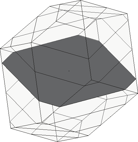
Wrench Capabilities of Planar Parallel Manipulators and their Effects Under Redundancy
121
polygons at different moments. For this problem, mz must be specified yielding the
following set of unknown variables:
T
x = [ f
f
τ
Thus, Eq. (8) is rearranged as follows:
x
y
t ] .
Ax = b
⎡ τ
⎤
1ext
1 0 −γ
⎡ f
⎢ # ⎥
⎡
⎤
⎤ ⎡γ
"
γ
γ
"
γ ⎤
⎡ ⎤
t
x
t−
t+
m
0
1,
1,1
1, 1
1, 1
1,
⎢τ
⎥
⎢
⎥ ⎢ ⎥ ⎢
⎥ t 1−
(9)
ext
0 1
f
⎢ ⎥
−γ
= γ
"
γ
γ
"
γ
⎢
⎥ −
⎢
t ⎥ ⎢ y ⎥
⎢
t−
t+
m
0
2,
2,1
2, 1
2, 1
2, ⎥
⎢ ⎥
⎢τ t+1ext ⎥
⎢0 0 −γ ⎥ ⎢τ ⎥ ⎢γ
"
γ
γ
"
γ ⎥
⎢ ⎥
⎣
⎦ ⎣ ⎦ ⎣
−
+
m
3, t
t
3,1
3, t 1
3, t 1
3, m ⎦ ⎢
#
⎥ ⎣ z ⎦
⎢τ
⎥
⎣ ext
m
⎦
The maximum available force pm
( F ) corresponds to the largest value of f that is evaluated
av
with the combinations, where
2
2
f = f + f
The maximum isotropic force pm
( F ) is
x
y .
is
determined as the shortest distance from the center of the force space to the polygon.
pm
pm
F an
F represent a point on an edge and a point on a facet of the polytope.
av
d
is
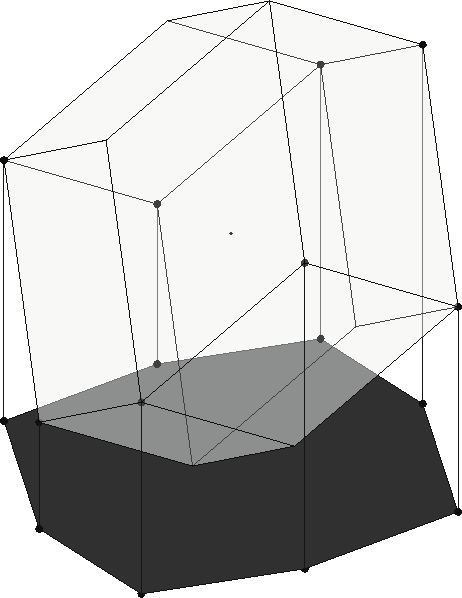
Maximum Allowable Force with an Associated Moment. If a moment does not affect the
requirement of the application, the manipulator can reach the largest available and isotropic
forces. To achieve these forces a particular moment must be associated with them. The set of
unknown variables of the Ax = b problem is
T
x = [ f
f
m
A force polygon may be
x
y
z ] .
generated by projecting the vertices of the polytope on the force plane. Fig 5 b illustrates the
projection of the polytope vertices on the force space plane. The available and isotropic
forces am
am
( F
F are respectively the longest and shortest distances from the center of
av and
is )
the force space to the projected polygon.
a)
b)
Fig. 5. Force analysis: a) Maximum force with a prescribed moment and b) Maximum force
with an associated moment.
4.3 Moment analysis
Maximum Moment with a Prescribed Force. For a fully described force ( f and α), the force
vector may be drawn within the polytope and the set of moments pf
( M ) that can be
z
reached with this force can be determined. Eq. (8) is rearranged as an Ax = b problem with
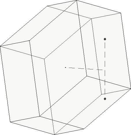
122
Parallel Manipulators, Towards New Applications
T
x = [ m τ
τ
The largest and smallest m
z
t
t ] .
a
b
z that can be obtained while keeping the
torques in transition within their capabilities define the range of pf M Fig. 6a illustrates an
z .
arbitrary force and the vertical line represents the range of moments.
Maximum Allowable Moment with an Associated Force. If the force does not affect the
application, the maximum range of moments af
( M ) has an associated force, i.e., a specific
z
force must be applied to achieve the largest moment. To find the maximum moment all the
actuators are set to their maximum capabilities. To achieve the largest range of af M , the
z
third row of Eq. (8) is arranged to obtain the combination of monomials that yields the
maximum and the minimum mz. Thus, only a single evaluation is required for each extreme
value. The highest and lowest vertices of the polytope represent this performance index.
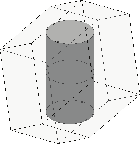
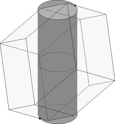
Maximum Moment with a Prescribed Isotropic Force. Assume that the manipulator is
required to apply or sustain the same force in all directions, i.e., an isotropic force fis. The
region of moments that can attain this force may be seen as a cylinder of radius fis that is
fully contained within the polytope, as shown in Fig. 6b. The range of moments pif
( M ) is
z
the height of the cylinder. The cylinder intersects facets of the polytope. This case cannot be
solved by simply rearranging Eq. (8). As an alternative, the maximum and minimum pif M
z
are determined by comparing the resulting isotropic moment associated with every plane of
the polytope. Isotropy is ensured with the plane that yields the minimum of the maximum
mz moment. A detailed formulation of this problem is described in Firmani et al. (2007a).
Maximum Moment with a Prescribed Available Force. Assume that the manipulator is
required to apply a large force regardless of its direction, i.e., available force fav. This case
may be seen as the intersection of a cylinder of radius fav with a point on the polytope which
is the farthest away from the mz=0 plane, as shown in Fig 6c. The range of moments paf
( M )
z
is the height of this cylinder. The cylinder usually intersects an edge of the polytope, but in
some particular cases the intersection may happen with a facet of a vertex of the polytope.
a)
b)
c)
Fig. 6 Moment analysis. Maximum moment with a prescribed a) Force, b) Isotropic force,
and c) Available force.
5. Wrench workspaces
5.1 Planar parallel manipulator architectures
For three-branch PPM layouts, there are seven possible architectures: RRR, RPR, PRR, RRP,
PPR, RPP, and PRP, where R and P denote a revolute and prismatic joint, respectively. Of
these seven architectures, the PRR and the RRP are kinematically equivalent. Likewise, the
Wrench Capabilities of Planar Parallel Manipulators and their Effects Under Redundancy
123
PPR and the RPP. Considering only one kinematically equivalent architecture yields only
five unique architectures. Eliminating those architectures with two prismatic joints, as they
are not convenient for implementation as PPMs, leaves only the RRR, RPR, and PRR
architectures to be studied. Based on these architectures, three actuation schemes are
analyzed: non-redundant PPMs, in-branch redundant PPMs, and branch redundant PPMs.
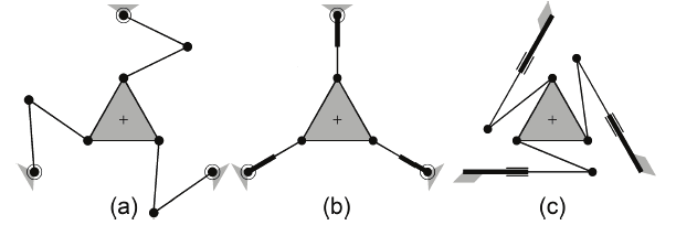
Non-Redundant PPMs. By considering the first joints actuated, the inertia of the mechanism
is kept low allowing manipulators to be used for high-speed applications. Thus, the
actuation layouts 3-RRR, 3-RPR, and 3-PRR are considered. Fig. 7 shows the schematics of
the three non-redundant PPM layouts. The fixed and mobile platforms are similar in every
case: the base triangle edge lengths are 0.5 m and the end-effector triangle edge lengths are
0.2 m. For the 3-RRR, the lengths of the first and second links of each branch are 0.2 m. The
torque limits of the actuators are ±4.2 Nm. For the 3-RPR, the torque limits are ±4.2 Nm and
the prismatic joints’ extension limits are 0.0 to 0.4 m. For the 3-PRR, the prismatic joints’
orientations are 0°, 120°, 240°, the prismatic joints’ extension limits are 0.0 to 1.0 m and the
force limits are ±10 N, while the lengths of the second links are 0.23 m.
Fig. 7. Non-redundant PPM layouts: a) 3-RRR, b) 3-RPR, c) 3-PRR
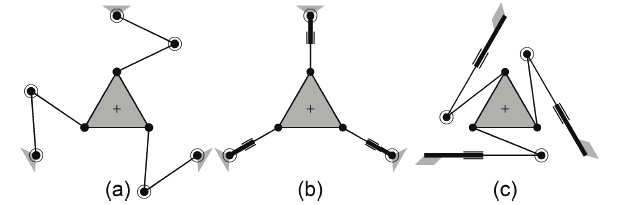
In-Branch Redundant PPMs. With this actuation scheme, the second joints of every branch
are actuated yielding the 3-RRR, 3-RPR, and 3-PRR layouts. Fig. 8 shows schematics of the
in-branch redundant PPM layouts. These PPMs have the same dimensions and actuator
capabilities as the ones used for the non-redundant PPMs. In addition, for the 3-RRR and the
3-PRR the second joint is actuated and the torque limits are ±2.1 Nm; whereas, for the 3-
RPR, the force limits of the prismatic joints are ±10 N.
Fig. 8. In-branch redundant PPM layouts: a) 3-RRR, b) 3-RPR, c) 3-PRR
Branch Redundant PPMs. An additional branch is added to the non-redundant PPMs
yielding the 4-RRR, 4-RPR, and 4-PRR layouts. The same dimensions and actuator
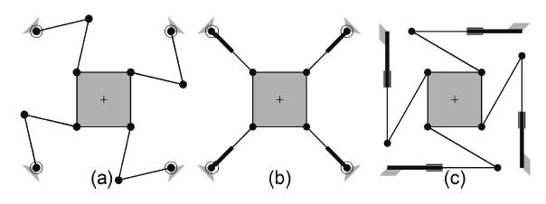
124
Parallel Manipulators, Towards New Applications
capabilities used for the non-redundant PPMs are employed for this analysis. For the 4-PRR,
the prismatic joints’ orientations are shown in Fig. 9c.
Fig. 9. Branch redundant PPM layouts: a) 4-RRR, b) 4-RPR, c) 4-PRR.
5.2 Wrench workspaces of planar parallel manipulators
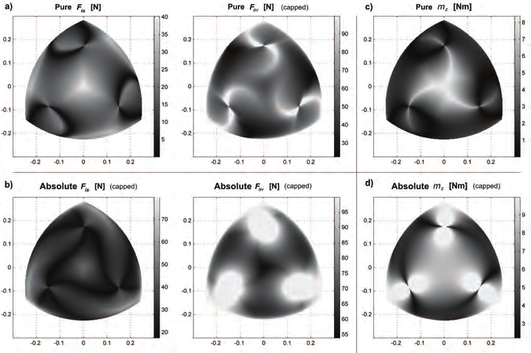
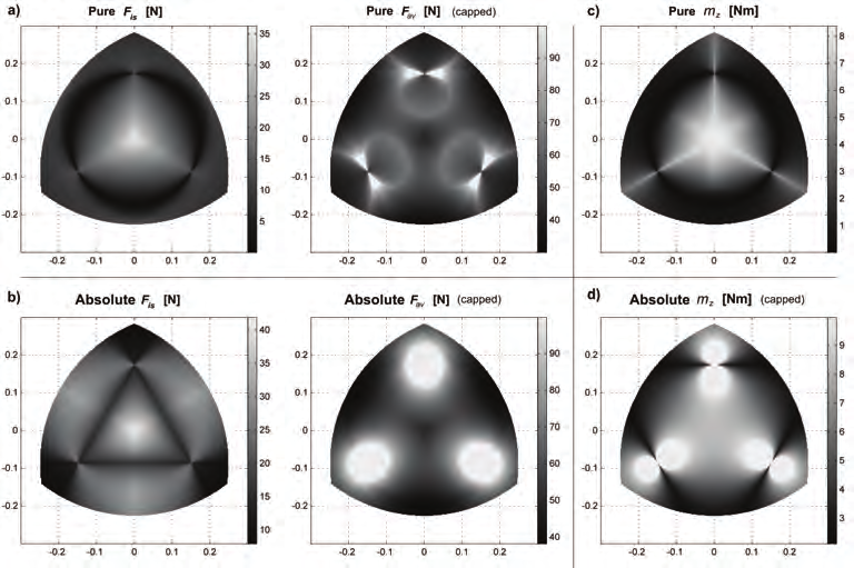
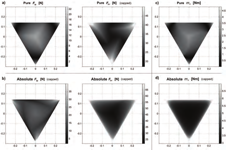
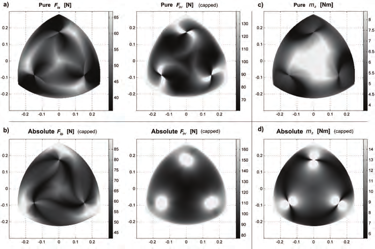
In this work, the platform orientations are held constant at 0° and the assembly modes for
the RRR and PRR architectures are shown in Figs. 7 to 9. Four analyses are considered:
a) Maximum force with a prescribed moment at mz = 0, i.e., pure force analysis,
b) Maximum allowable force with an associated moment , i.e., absolute force analysis,
c) Maximum moment with a prescribed force at f = 0, i.e., pure moment analysis,
d) Maximum allowable moment with an associated Force , i.e., absolute moment
analysis.
The third analysis ( f = 0) is a special case that also involves the operational condition of
prescribed isotropic and available forces. Examples of prescribed isotropic and available
forces workspaces, where f ≠ 0, can be found in Firmani et al. (2007b).
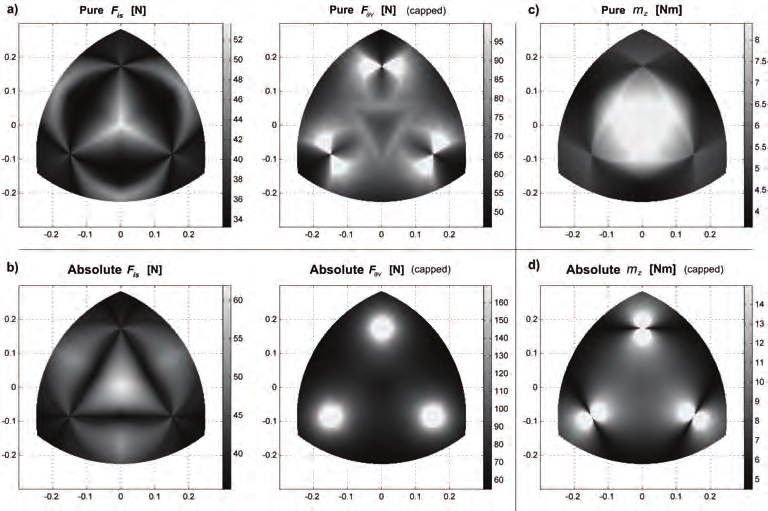
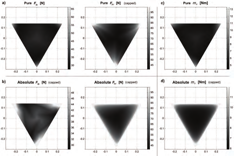
Figs. 10 to 18 show the wrench capabilities of the previously described manipulators. These
capabilities are presented in two dimensional plots whose axes indicate the location of the
mobile platform throughout the workspace [m]. At each location, either the maximum force
or maximum moment capability is determined and illustrated with a dot using a grayscale
gradient. Nonetheless, some of the magnitudes were very large compared to the rest of the
results in the workspace. Large values are caused by the proximity of the manipulator to a
singular configuration and this spoils the overall grayscale gradient.
Parallel manipulators are affected by inverse and direct singularities. An inverse singularity
configuration usually occurs at the boundaries of the workspace. For the RRR architecture, a
branch is either fully extended or folded back. For the RPR architecture, the displacement of
a prismatic joint is zero. For the PRR architecture, the second link of a branch is
perpendicular to the prismatic joint. Under these configurations, the manipulator cannot
apply any force along one direction, but in theory it can sustain an infinite load. Similarly,
the manipulator cannot apply any moment but in theory it can sustain an infinite moment, if
an associated force goes to infinity. Since infinite wrench magnitudes would destroy the
grayscale gradient, hence, the authors opted to cap these values.
A direct singularity occurs when the branch resultant forces together do not span an
external wrench, i.e., the branch resultant forces intersect at a common point (planar pencil).
If the branch forces intersect at infinity, an external force, normal to the branch forces,
cannot be sustained, i.e., f = If the intersection occurs somewhere else, an external
is
0.
moment applied to the mobile platform cannot be balanced by the actuators, i.e., mz = 0.
Wrench Capabilities of Planar Parallel Manipulators and their Effects Under Redundancy
125
Fig. 10. Wrench workspaces for the 3-RRR PPM.
Fig. 11. Wrench workspaces for the 3-RPR PPM.
126
Parallel Manipulators, Towards New Applications
Fig. 12. Wrench workspaces for the 3-PRR PPM.
Fig. 13. Wrench workspaces for the 3-RRR PPM.
Wrench Capabilities of Planar Parallel Manipulators and their Effects Under Redundancy
127