Parallel manipulators (PMs) are closed kinematic chains with one or more loops where only
some pairs are actuated while the remaining are passive. In particular, they feature a fixed
link (base) and an output moving link (platform) interconnected by at least two independent
kinematic chains (legs) to form one loop. The most well known and commonly employed
PMs (hereafter called UPS-PMs) feature n variable-length legs of type UPS (where U, P and
S are for universal, spherical and prismatic pairs respectively). Equivalently, a revolute pair
R could be used instead of the prismatic pair P in order to make the leg length variable (in
this case the leg would be of type URS). These leg topologies provide the platform with six
degrees of freedom with respect to the base.
Although the definition of UPS-PMs requires n ≥ 2, in practice, neglecting overconstrained
and redundantly-actuated manipulators, performance issues recommend 3 ≤ n ≤ 6. Indeed,
UPS-PMs with only two UPS legs might exhibit a low stiffness against torques acting along
the line joining the centers of the two spherical pairs, and their control would require the in-
series placement of at least three actuators/sensors (one of them placed to control/measure
at least one out of the three degrees of freedom of the spherical pairs) which reduces the
overall manipulator dynamic and accuracy capabilities. On the other side, the use of more
than six legs reduces the exploitable manipulator workspace for the increase of leg
interference.
Different sub-classes of manipulator architectures can be obtained according to the location
of the centers of the U and S pairs in the base and in the platform respectively (Innocenti &
Parenti-Castelli, 1994; Faugere & Lazard, 1995). General UPS-PM architectures feature
distinct joint centers. Special architectures can be devised by setting some of the joint centers
to be coincident.
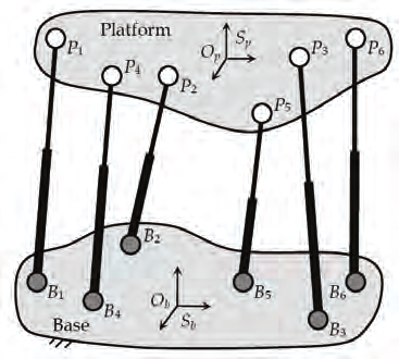
A schematic of a 6-DOF UPS-PM having six legs ( n = 6) and general architecture is shown in
Fig. 1. In the figure, the U pairs (connecting the legs to the base) and S pairs (connecting the
legs to the platform) are depicted as grey and white dots respectively. Points Bi and Pi
represent the centers of the U and S pairs of the i-th leg on the base and on the platform
respectively. The six legs of type UPS are represented by the telescopic rods BiPi ( i = 1, …,
6). Accordingly, the length of the i-th leg is defined as the distance li = ⎪ Pi - Bi⎪.
134
Parallel Manipulators, Towards New Applications
Fig. 1. Parallel manipulator with six legs of type UPS
Manipulators with less than six DOF can be obtained from UPS-PMs by suitably eliminating
or locking some of the leg kinematic pairs. For instance, considering a 6-DOF UPS-PM
having six legs, elimination of four P pairs yields a 2-DOF PM having two legs of type UPS
and four legs of type US.
Well-known examples of UPS-PMs are as follows: 1) the 6-DOF UPS-PMs (Gough &
Whitehall, 1962; Stewart, 1965; Cappel, 1967); 2) the 3-DOF spherical PMs (Innocenti &
Parenti-Castelli, 1993); 3) the 2-DOF spherical PMs (Vertechy & Parenti-Castelli, 2006); and
4) the 1-DOF helicoidal PMs (Jacobsen, 1975). Because of their parallel architecture,
UPS-PMs exhibit large payload-to-weight ratio, high accuracy, high structural rigidity and
high dynamic capabilities, which make them excel as: a) fast and high precision robots in
vehicle simulators (Gough & Whitehall, 1962; Stewart, 1965; Cappel, 1967), machine tools
(Charles, 1995) and positioning systems (Schmidt-Kaler, 1992); b) passive Cartesian input
devices in joysticks, master-slave teleoperation systems (Daniel et al., 1993) and other
tracking devices (Geng & Haynes, 1994); c) force/torque sensors and generators in multi-
axis sensors and motors (Gaillet & Reboulet, 1983; Nguyen et al., 1991; Lewis et al., 2002);
d) mechanical transmissions in motion converters (Jacobsen, 1975); and e) orthopedic
devices in fixations systems (Taylor & Taylor, 2000; Di Gregorio & Parenti-Castelli, 2002).
Practical use of UPS-PMs requires solving the manipulator direct position analysis (DPA)
robustly, quickly and accurately. By definition, the DPA of PMs consists in finding the
relative pose (position and orientation) of platform and base when the readouts of an
adequate number of joint-sensors (hereafter also referred to as “input variables”), which
equip some of the leg kinematic pairs, are given. Usually, this problem involves the solution
of a system of kinematic constraint equations (SKCE) that are implicit and non-linear. That
is, in general, the DPA of UPS-PMs is very complicated and admits multiple real solutions,
each corresponding to a different mode of assembly of the manipulator. The existing
methods for the solution of the DPA of UPS-PMs fall into three categories: 1) echelon-form
approaches (Griffis & Duffy, 1989; Innocenti & Parenti-Castelli, 1990; Nanua et al., 1990;
Merlet, 1992; Innocenti, 2001; Lee & Shim, 2001); 2) iterative approaches (McCallion &
Truong, 1979; Reboulet, 1988; Innocenti & Parenti-Castelli, 1991; Merlet, 1993a; Parenti-
Robust, Fast and Accurate Solution of the Direct Position Analysis of
Parallel Manipulators by Using Extra-Sensors
135
Castelli & Di Gregorio, 1995; McAree & Daniel, 1996); and 3) extra-sensor approaches. Both
echelon-form methods and iterative methods are based on the use of a number of input
variables (that is the joint-sensor number) which equals the number of manipulator DOFs.
They differ, however, in the way the SKCE is solved. In particular, in echelon-form
approaches, the SKCE is possibly reduced to one univariate polynomial equation, from
which all the possible modes of assembly of the manipulator are determined by means of
standard root finding techniques. Though of great theoretical significance, echelon-form
methods are not suited for real-time applications where the fast and unambiguous
identification of the actual pose of the platform is sought for. In iterative approaches, the
SKCE is solved monolithically by iterative techniques, mostly based on the Newton-
Raphson method. These approaches require a guess solution and aim at determining the
actual pose of the platform in real-time. Unfortunately, iterative approaches require both the
UPS-PM to be sufficiently far away from a singular configuration and a good initial guess of
the actual pose of the platform, two conditions which cannot always be satisfied and can
seriously affect the robustness of these approaches. Unlike the first two methods, extra-
sensor approaches use a number of input variables which is greater than the number of
manipulator DOFs. The extra-sensors are added for at least one of the following reasons:
1) to render the SKCE an explicit problem, which makes it possible to find closed form
solutions of the DPA; 2) to render the SKCE a linear problem, which makes it possible to
find the actual pose of the platform unambiguously; 3) to speed-up the computation of the
DPA solution; 4) to make the method robust against UPS-PM special configurations (i.e.
platform poses for which the DPA problem becomes undetermined); and 5) to improve the
accuracy of the solution by reducing the influence of the errors affecting the joint-sensor
readouts on the errors affecting the computed actual pose of the platform.
A proper choice of the number, type and location of the sensors makes it possible to devise
extra-sensor methods possessing all the abovementioned features. The possibility of
determining the actual configuration of the UPS-PM (i.e. the actual platform pose)
unambiguously, robustly, quickly and accurately makes such extra-sensor approaches
superior to the echelon-form and the iterative ones in practical real-time applications.
In this chapter, a detailed overview of the extra-sensor approaches, presented in the
literature, is first provided. Then a novel very robust, fast and accurate general method
based on extra-sensors is presented which makes it possible to unambiguously find the
actual pose of the platform of UPS-PMs having general architecture. The method readily
applies also to the DPA of both UPS-PMs with special geometry and PMs with less than six
DOF that can be obtained from the 6-DOF UPS-PMs by suitably eliminating or locking some
of the leg kinematic pairs. Finally, discussions are reported to highlight the advantages of
the presented method.
2. Measurement of the input variables for the DPA of UPS-PMs
The manipulator DPA requires the knowledge of a number of input variables at least equal
to the number of manipulator DOF. The manipulator variables which are frequently chosen
as input for the solution of the DPA of UPS-PMs are presented in this section along with the
possible methods for their measurement.
Considering UPS-PMs having n legs, possible choice (which practically the most used) of the
input variables are the followings:
136
Parallel Manipulators, Towards New Applications
- the joint variables of the n existing legs of the manipulator;
- the distance between points of suitably chosen links.
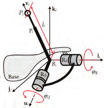
Fig. 2. Leg of type UPS
In the first case, sensors are located on the leg kinematic pairs. For instance, with reference
to Fig. 2, the sensors can measure the leg joint variables, i.e. the angles ϕ i 1 and ϕ i 2 ( i = 1, …, n) and the lengths li = ⎪ Pi - Bi⎪ of the U and P pairs. Conversely, the spherical pairs are
normally not instrumented since, unless they are manufactured as three revolute pairs with
intersecting axes, the installation of rotary sensors may be impractical. Moreover, as a matter
of fact, because of their own bulk, weight, vulnerability and cabling, sensors should be
placed as close as possible to the base in order to not decrease manipulator performance,
ruggedness and reliability.
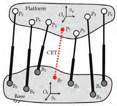
Fig. 3. Parallel manipulator with six legs of type UPS and one string pot
Robust, Fast and Accurate Solution of the Direct Position Analysis of
Parallel Manipulators by Using Extra-Sensors
137
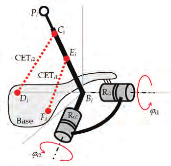
Fig. 4. Leg of type UPS instrumented with string pots
In the second case, additional external sensors are used. The most common way is to use:
a) cable extension transducers (CET, also known as “string pots”);
b) passive chains of type UPS with a sensor embedded in the P pair.
By means of these sensors, the distance between points of the base and the platform can be
measured (see Fig. 3, points B 7 and P 7) or also the distance of points of suitably chosen links
of the UPS legs can be measured, which may provide additional information on the joint leg
variables. For instance, (see Fig. 4) the measure of ⎪ Ci - Di⎪ and ⎪ Ei - Fi⎪, with Di and Fi points of the platform, and Ci and Ei points of the second movable link of the UPS leg,
indirectly provides the values of the joint angles ϕ i 2 and ϕ i 1. It is worth noting, however, that
the direct measuring of angles ϕ i 1 and ϕ i 2 by rotary sensors (placed locally on the revolute
pairs) is normally preferable since it would lead to a unique position of point Pi, while the
use of the lengths of the segments CiDi and EiFi would provide two positions for Pi (two
symmetric positions with respect to the plane defined by points Bi, Di and Fi).
The choice of the UPS joint variables is, in general, the most suitable. Indeed, the addition of
CETs or additional UPS measurement legs can both reduce the exploitable manipulator
workspace (because of increased possibility of leg interference) and slow-down the
manipulator dynamic performance (due to the inertia of the additional UPS legs and to the
limited mechanical response of CETs). Moreover, CET sensor accuracy is poor for many
practical applications and the implementation of accurate extra UPS measurement legs is
rather expensive.
An overview of extra-sensor based methods that have been proposed in the literature for the
DPA of 6-DOF UPS-PMs having general architecture is presented in the following section.
Of course, all these methods readily apply to the DPA of both UPS-PMs with special
geometry and PMs with less than six DOF that can be obtained from the 6-DOF UPS-PMs by
suitably eliminating or locking some of the leg kinematic pairs.
3. Literature overview of extra-sensor based methods for the DPA of UPS-
PMs
This section provides an overview of extra-sensor based methods that are available for the
solution of the DPA of 6-DOF UPS-PMs. The methods are sorted in chronological order
138
Parallel Manipulators, Towards New Applications
(according to the publication date of the author’s most relevant work). For each method, the
employed sensor layouts are first described, and the major features and drawbacks of the
resulting DPA methods are then highlighted. To describe the sensor layout of each leg of
type UPS, the sequence RRP is used to indicate the cascade of joints which are serially
connected from base to platform (referring to Fig. 2, RR indicates the two revolute pairs with
intersecting axes the U pair is featured by; the spherical pair S is ignored since it is not
supposed to be instrumented) and the underline is used to highlight the joint whose
position is measured. For instance, the leg sensor layout RRP indicates that 1 rotary position
sensor and 1 linear position sensor are installed on the leg. The sensor layout of a given
manipulator is described by a list (set) of sensor layouts of the legs belonging to the
manipulator. That is, the set {2-RRP, RRP, 4-RRP} indicates that 8 sensors are mounted on
the manipulator; in particular, it features 2 legs each having 1 rotary position sensor, 1 leg
having 1 rotary position sensor and 1 linear position sensor, and 4 legs each having 1 linear
position sensor.
The first DPA solution of UPS-PMs via extra-sensors was firstly proposed in 1991, when,
following the studies on the pose and twist estimation from three collinear measured points
(Fenton & Shi, 1989), Shi and Fenton (Shi & Fenton, 1991) employed the set {3-RRP} to
devise a method that reduces the DPA of UPS-PMs having general base and platform to an
explicit problem which can be readily solved in real-time. Irrespective of the manipulator
configuration, the method always makes it possible to find the actual platform pose.
However, the method does not account for the measurement errors, which in practice
always affect the sensor readouts. As a matter of fact, the proposed method is rather
inaccurate when measurement errors are present.
Several sensor layouts are studied in (Stoughton & Arai, 1991) in order to devise fast and
accurate methods for the solution of the DPA of the UPS-PM with general base and
platform. Note that results similar to those presented by Stoughton and Arai have also been
reported lately in (Hesselbach et al., 2005). In particular: 1) using the set {3-RRP} the DPA is
reduced to an explicit problem readily yielding the actual manipulator configuration; 2)
using both the set {2-RRP, RRP} and the set {2-RRP, RRP} the DPA is reduced to the solution
of a system of 2 uni-variate quadratic equations in the same unknown usually yielding the
actual manipulator configuration; 3) using both the set {2-RRP, RRP} and the set {2-RRP,
RRP} the DPA is reduced to the solution of a system of 2 quadratic and 1 linear 3-variate
equations in the same 3 unknowns usually yielding 2 possible manipulator configurations
from which the actual platform pose cannot be detected; 4) using one of the sets {RRP,
2-RRP}, {RRP, 2-RRP} or {RRP, RRP, RRP}, the DPA is reduced to the solution of 2 uni-
variate quadratic equations in 2 different unknowns usually yielding four possible
manipulator configurations (although it is not stated in the paper, the actual manipulator
configuration may be detected among those 4 possibilities by checking the satisfaction of a
further constraint equation); and 5) using the set {RRP, RRP, RRP} the DPA is reduced to the
sequential solution of a system of 2 quadratic and 1 linear 3-variate equations in the same 3
unknowns, and of a uni-variate quadratic equation in a different unknown usually yielding
4 possible manipulator configurations among which the actual platform pose cannot be
detected. All the aforementioned solutions can be computed in real-time. Only the method
based on the set {3-RRP} guarantees that the actual manipulator configuration can always be
calculated (manipulator configurations may exist for which the methods based on the other
sensor layouts cannot find a unique DPA solution). The paper also addresses accuracy
Robust, Fast and Accurate Solution of the Direct Position Analysis of
Parallel Manipulators by Using Extra-Sensors
139
issues. In particular, the ratios between the magnitudes of the errors affecting the computed
manipulator configuration and the measurement errors affecting the joint-sensor readouts
are determined for all the abovementioned sensor layouts. This makes it possible to select
the required sensor precision which provides the desired accuracy of the calculated platform
pose. Moreover, it is shown that the solution of the DPA based on the set {3-RRP} is less
sensitive to the measurement errors affecting the joint-sensors than the solution which can
readily be computed if the measurement of the 6 joints parameters of one single leg are
available (in this latter case the leg sensor layout would be RRP plus 3 additional rotary
position sensors measuring the rotations allowed by the S pair of the same leg).
Two sensor layouts are proposed in (Cheok et al, 1992) to devise methods that make it
possible to find the actual solution of the DPA of the UPS-PM with general base and
platform in real-time. In particular: 1) using the set {3-RRP} the DPA is reduced to an explicit
problem readily yielding the actual manipulator configuration; and 2) using the set {6-RRP,
RRP} the DPA is reduced to the solution of a system of 6 linear 6-variate equations in the
same 6 unknowns usually yielding the actual manipulator configuration. Only the method
based on the set {3-RRP} guarantees that the actual manipulator configuration can always be
calculated. Indeed, special manipulator configurations may exist for which the 6 linear
equations to be solved in method (2) are not linearly independent. The paper does not
address accuracy issues. As a matter of fact, the proposed method is rather inaccurate when
the joint-sensors are affected by measurement errors.
Two sensor layouts are proposed in (Merlet, 1993b) to devise methods that make it possible
to find the solution of the DPA of UPS-PMs in real-time. In particular: 1) the set {2-RRP,
2-RRP} is used to reduce the DPA of the UPS-PM with general base and platform to the
solution of a system of 2 uni-variate quadratic equations in the same unknown usually
yielding the actual manipulator configuration; 2) the set {RRP, RRP, 2-RRP} is used to
reduce the DPA of the UPS-PM with general base and platform to the sequential solution of
a system of 2 uni-variate quadratic equations in the same unknown and of a uni-variate
quadratic equation in a further different unknown usually yielding 2 possible manipulator
configurations from which the actual platform pose cannot be detected; and 3) the set {RRP,
6-RRP} is used to reduce the DPA of the UPS-PM with planar base and platform to the
solution of a system of 9 9-variate linear equations in the same 9 unknowns usually yielding
the actual manipulator configuration. Note that the proposed methods do not guarantee that
the actual manipulator configuration can always be calculated. Indeed, special manipulator
configurations may exist for which either the two pairs of solutions of the two quadratic
equations to be solved in method (1) are identical or the 9 linear equations to be solved in
method (3) are not linearly independent. Accuracy issues related to the {2-RRP, 4-RRP}
sensor layout are addressed in a later paper (Tancredi and Merlet, 1994) in which the pose
dependent ratios between the magnitudes of the errors affecting the computed manipulator
configuration and the errors affecting the joint-sensor readouts are evaluated and mapped.
Two sensor layouts are proposed in (Nair & Maddocks, 1994) to devise methods that make
it possible to reduce the solution of the DPA of UPS-PMs to an explicit problem which can
be solved in real-time. In particular: 1) the set {16-RRP} is used to reduce the DPA of
manipulators with general base and platform to the solution of a system of 16 16-variate
linear equations in the same 16 unknowns usually yielding the actual manipulator
configuration; and 2) the set {9-RRP} is used to reduce the DPA of manipulators with planar
base/platform to the solution of a system of 9 9-variate linear equations in the same 9
140
Parallel Manipulators, Towards New Applications
unknowns usually yielding the actual manipulator configuration. None of the proposed
methods guarantee that the actual manipulator configuration can always be calculated.
Indeed, special manipulator configurations may exist for which either the 16 linear
equations to be solved in method (1) or the 9 linear equations to be solved in method (2) are
not linearly independent. The paper does not address accuracy issues. As a matter of fact,
the proposed method is rather inaccurate when the joint-sensors are affected by
measurement errors.
A method is proposed in (Jin, 1994), which uses the set {4-RRP, 2-RRP}, to reduce the DPA of
the UPS-PM with planar base and platform to the sequential solution of a system of 2 linear
2-variate equations in the same 2 unknowns and of a system of 5 5-variate linear equations
in a further 5 unknowns. The problem can be solved in real-time and usually admits one
solution corresponding to the actual manipulator configuration. The proposed method does
not guarantee that the actual manipulator configuration can always be calculated. Indeed,
special manipulator configurations may exist for which either the 2 equations belonging to
the first system to be solved or the 5 equations belonging to the second system to be solved
are not linearly independent. The paper does not address accuracy issues. As a matter of
fact, the proposed method is rather inaccurate when the joint-sensors are affected by
measurement errors.
A study for the determination of the maximum number of possible DPA solutions for UPS-
PMs having different sensor layouts was accomplished in (Tancredi et al., 1995). It turned
out that: 1) the DPA of UPS-PMs with general base and platform admits up to 35 possible
solutions when the set {5-RRP, RRP} is used; 2) the DPA of UPS-PMs with general base and
platform admits up to 8 possible solutions when the set {3-RRP, 3-RRP} is used; 3) the DPA
of UPS-PMs with planar base and platform admits up to 6 possible solutions when the set
{RRP, 5-RRP} is used; 4) the DPA of UPS-PMs with planar base and platform admits up to 4
possible solutions when the set {6-RRP} is used; and 5) the DPA of UPS-PMs with general
base and platform admits up to 8 possible solutions (however, only two solutions are more
likely) when the set {5-RRP, RRP} is used.
A method is proposed in (Etemadi-Zanganeh & Angeles, 1995), which uses the set {5-RRP,
RRP}, to reduce the DPA of the UPS-PM with general base and platform to the solution of 5
eigenproblems of 6 × 6 matrices usually admitting a unique solution which can be computed
in real-time. Note that the proposed method does not guarantee that the actual manipulator
configuration can always be ca