construction”,International Journalof Robotic Resarch, Vol. 5, pp. 157-182.
Griffis, M., and Duffy, J., ”A Forward Displacement Analysis of a Class of Stewart
Platforms,” Trans. ASME Journal of Mechanisms, Transmissions, and A utomation
in Design, Vol. 6, No. 6, June 1989, pp. 703-720.
Affi Z., Romdhane L. and Maalej A., 2004. Dimensional synthesis of a 3-translational-DOF
in-parallel manipulator for a desired workspace. European Journal of Mechanics -
A/Solids, Vol 23, Issue 2, pp 311-324.
Clavel, R. 1986. Une nouvelle structure de manipulation parallèle pour la robotique légère.
R.A.I.R.O. APII, Vol 23, N° 6.
Vischer P. and Clavel R. 1998,”Kinematic Calibration of the Parallel Delta Robot”, Robotica,
16, pp. 207-218.
M. Stock and K. Miller 2003, ”Optimal Design of Spatial Parallel Manipulators: Application
to linear Delta Robot”, ASME Journal of Mechanical Design, Vol. 125, pp 292–301.
Hervé J. M. 1995, “Design of Parallel Manipulators via Displacement Group”, Proceedings
of the 9th World Congress on the Theory of Machines and Mechanisms. pp. 2079-
2082.
Hervé, J. M., Sparacino F. 1991. Structural synthesis of parallel robots generating spatial
translation. 5th Int.Conf. On Adv. Robotics, IEEE n°91TH0367-4, Vol. 1, pp 808-813.
Romdhane, L. 1999, Design and analysis of a hybrid serial-parallel manipulator. Mechanism
and Machine Theory, Vol. 34, Issue 7, pp 1037-1055.
Romdhane, L., Affi Z., Fayet M., 2002. Design and singularity analysis of a 3 translational-
DOF in-parallel manipulator. ASME Journal of Mechanical Design, Vol. 124, pp
419–426.
A. Tremblain and L. Baron 1999, ”Geomatrical synthesis of parallel manipulators of star-like
topology with a geometric algorithm”, IEEE International Conference on Robotics
and Automation, Detroit, MI.
Tsai L-W 1996,“Kinematics of three-dof platform with three extensible limbs” In J. Lenarcic
V. Parenti-Castelli, editor, Recent Advances in Robot Kinematics, pp 401 410,
Kluwer.
C. Gosselin,1990, ”Determination of the workspace of 6-dof parallel manipulators”, ASME
Journal of Mechanical Design, Vol. 112, pp. 331-336.
Advanced Synthesis of the DELTA Parallel Robot for a Specified Workspace
223
L. Romdhane,1994, ”Orientation workspace of fully parallel mechanisms”, Eur. J. of
Mechanics Vol. 13, pp. 541-553.
R. Boudreau and C. M. Gosselin 1999, ”The synthesis of planar parallel manipulators with a
genetic algorithm”, ASME Journal of Mechanical Design, Vol 121, pp 533-537.
R. Boudreau and C. M. Gosselin 2001, ”La synthèse d’une plate forme de Gough-Stewart
pour un espace de travail atteignable prescrit”, Mech. Mach. Theory 36 (2001) 327-
342.
Kosinska, A, Galicki, M. and Kedzior, K. 2003,”Design and optimization of parameters of
Delta-4 Parallel Manipulator for a Given Workspace”, Journal of Robotic Systems
20 (9), pp 539-548.
J. A. Snyman and A. M. Hay 2005, ”Optimal synthesis for a continuos prescribed dexterity
interval of 3-DOF parallel planar manipulator for different prescribed output
workspaces”, Proceeding of CK2005, 12th International Workshop on
Computational Kinematics Cassino May 4-6.
M. Gallant and R. Boudreau 2002, ”The synthesis of planar parammel manipulators with
prismatic joints for an optimal, singularity-free workspace”, Journal of Robotic
Systems 19 (1), pp 13-24.
F. Pierrot, C. Reynau and A. Fourier 1990, ”DELTA : a simple and efficient parallel robot”,
Robotica Vol. 8, pp 105-109.
Goudali, A. 1995. Contribution à l’étude d’un nouveau robot Parallèle 2- Delta à six degrés
de liberté avec découplage. Thèse de doctorat Génie Mécanique L.M.S. Poitiers.
France.
J.P. Lallemand, A. Goudali and S. Zeghloul, ”The 6 - D.o.f. 2 - Delta parallel robot” ,
Robotica Journal, Vol. 15, pp 407-416, 1997.
Goldberg, D.E., 1994, Genetic Algorithms in Search, Optimization, and Machine Learning,
Addison-Wesley Publishing, Reading, MA.
Chipperfield A., Fleming P., Pohlheim H. and Fonseca C. 1994, ”Genetic
AlgorithmTOOLBOX user’s Guide” Department of automatic control and systems
engineering university of Sheffield version (v 1.2)
J.A. Lozano , P. Larranaga, M. Grana, F.X. Albizuri 1999, Genetic algorithms: bridging the
convergence gap, Theoretical Computer Science Vol. 229, pp 11-22.
R. Chelouah, P. Siarry 2000, A continuous genetic algorithm designed for the global
optimization of multimodal functions, Journal of Heuristics Vol. 6, pp. 191-213.
Schmitt L. M. 2001, Fundamental Study Theory of genetic algorithms, Theoretical Computer
science n°259 pp 1-61.
Laine, R., Zeghloul, S., Ramirez, G., 2002, A Method based on a Genetic Algorithm for the
Optimal Design of Serial Manipulators, Int. Symp. Rob. and Aut., pp. 15-20, Toluca,
Mexique.
M.A. Laribi, A. Mlika, L. Romdhane and S. Zeghloul, 2004,”A Combined Genetic Algorithm-
Fuzzy Logic Method (GA-FL) in Mechanisms Synthesis”, Mech. Mach. Theory 39,
pp. 717-735.
Coxeter, H. S. M.1969, ”Introduction to Geometry”, 2nd ed. New York: Wiley.
Alden H. Wright, 1991,”Genetic algorithms for real parameter optimization, Foundations of
Genetic Algorithms”, (edited by Gregory J. E. Rawlins), Morgan Kaufman, pp. 205-
218.
Steiner, J., 1826 ,”Einige geometrische Betrachtungen.” J. reine angew. Math. 1, pp. 161-184.

224
Parallel Manipulators, Towards New Applications
A Appendix
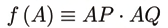
The power of a fixed point A (see Figure 17) with respect to a circle of radius r and center O
is defined by the product
Where, P and Q are the intersections of a line through A with the circle. The term ”power”
was first used in this way by Jacob Steiner [33,31]. f ( A) is independent of the choice of the
line APQ.
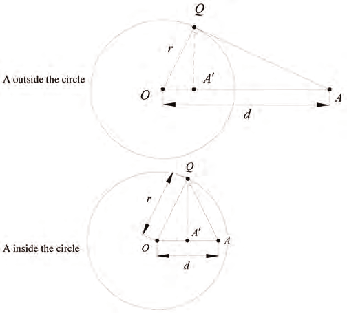
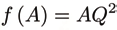
Now consider a point A (see Figure 17) not necessarily on the circumference of the circle. If d
= OA is the distance between A and the circle’s center O with equation f ( x, y) = x2 + y2 − r2 =
0, then the power of the point A relative to the circle is givn by :
Fig. 17: The power of the point.
If A is outside the circle, its power is positive and it is equal to the square of the length of the
segment AQ from A to the tangent Q to the circle through A,
If A is inside the circle, then the power is negative.
11
Size-adapted Parallel and Hybrid Parallel
Robots for Sensor Guided Micro Assembly
Kerstin Schöttler, Annika Raatz and Jürgen Hesselbach
Technische Universität Braunschweig, Institute of Machine Tools and Production
Technology (IWF), Langer Kamp 19 B, D-38106 Braunschweig
Germany
1. Introduction
Miniaturized products and components are part of today’s daily life. The comfort and
security of automobiles is increased by use of micro sensors and actuators. Electronic
devices, such as mobile phones and MP3-players, have reached very small sizes and
miniaturized medical instruments facilitate endoscopic surgery.
Due to the advantages of micro technological solutions, such as small dimensions and low
weight, Micro Systems Technology (MST) is worldwide considered a key technology of the
21st century. The new NEXUS market analysis forecasts a yearly growth of the world
markets of 16% for products based on MST (Wicht & Bouchaud, 2005).
Miniaturization and simultaneous function integration are leading to increased
requirements regarding production technology as a result of scaling effects, technical and
assembly related problems (van Brussel et al., 2000). For MST products, micro assembly
uncertainties in the range of a few micrometers or even less than one micrometer are
required.
1.1 Approaches to meet the requirements for micro assembly
At present industrial applications for micro assembly predominantly incorporate systems
which were originally developed for 2D chip assembly in semi-conductor back-end
production. They can be classified into three groups according to their attainable assembly
uncertainty. Most of the positioning units of the first class are pick-and-place machines
based on Cartesian axes with uncertainties between 30 µm and 60 μm at 3σ. The second
group, die-bonding machines, reaches pick-and-place uncertainties of 10 µm to 12 μm at 3σ
by means of high-precision linear drives, high-resolution camera systems as well as systems
for controlling and compensating for influences caused by changing temperatures. Ultra-
precision die-bonders form the third class. They can be regarded as special machines for
specific applications which were developed for the assembly of micro-optical components,
optical fibres and especially for flip-chip assembly. They reach assembly or pick-and-place
uncertainties of about 1 μm at 3σ. These low uncertainties can only be achieved with the
help of special camera systems and positioning strategies. At present, these assembly
uncertainties are always tied to a highly customized design of the assembly system adjusted
226
Parallel Manipulators, Towards New Applications
to the requirements of the products. This way the assembly uncertainties described are
reached at the expense of a very low flexibility (Raatz & Hesselbach, 2007).
For the design of micro assembly systems it is necessary to gain a high product flexibility of
the assembly units. Solutions that provide enough flexibility to reconfigure the system
design need to be found. Here, modularity is the key when striving for high flexibility of the
number of quantities, product variants and manufacturing base. The precision robot
represents the central component within the assembly system. Some fundamental
techniques to lower the uncertainty of the precision robot and the assembly system are
choosing an adequate kinematic structure, developing size adapted handling devices,
integrating ultra-precision machine elements and/or using sensor guidance (Fig. 1).
Increased accuracy
Precision
Kinematic
Size adapted
Ultra-precision
robot
structure
handling devices
machine elements
Assembly
Sensor
Precise peripherie
...
system
guidance
(gripper, feeder)
Fig. 1. Approaches to meet the requirements of accuracy (Raatz & Hesselbach, 2007)
1.2 Kinematic structures
Robots can be classified in terms of their kinematic structure into serial, parallel and hybrid
(serial/parallel) robots. Most industrial robots are based on a serial structure between the
frame and the working platform. All joints of open kinematic chains have a single degree of
freedom (DOF) and are active, i.e. they are actuated. The serial structure offers in principle a
large workspace in relation to the size of the robot as well as a high orientation range. The
relatively large moved masses are a disadvantage of serial structures regarding the
dynamics and accuracies of the robot, since each drive must be moved along with the entire
kinematic chain. In micro assembly, large moved masses lead to massive construction of the
frames and the robot links related to the size of the assembled parts.
Parallel robots are based on closed kinematic chains, i.e. they have several guiding chains
between the base frame and the working platform, which provide a high structural stiffness.
It is possible to install all drives in a fixed frame or at least to locate them nearby the frame,
which results in low inertia. Drive positioning errors or tolerances in the legs are not
necessarily added. Usually they partially compensate each other and only affect the
positioning uncertainty of the end effector to a small extent.
Parallel robots are well suited for highly precise handling operations, due to their high
structural stiffness with low moved masses at the same time. Compared to serial robots, the
miniaturization of a parallel robot is much easier because all joints are passive. In addition
the passive joints offer the potential for integrating flexure hinges as ultra-precision machine
elements. The small workspace compared to the robot dimensions does not become severe
in micro assembly tasks due to the size of the objects.
Combining a parallel structure with a serial structure the limited and position dependent
mobility of the end effector can be overcome. For example by integrating a serial rotational
axis into the working platform of a parallel robot, the end effector can be very well oriented.
Size-adapted Parallel and Hybrid Parallel Robots for Sensor Guided Micro Assembly
227
1.3 Robots for micro assembly
A number of commercial robot manufacturers and many research institutions are
developing robots which have sufficient positioning uncertainties for micro assembly tasks.
Serial, parallel and hybrid robot structures are used. Most serial robots for micro assembly
use a Cartesian structure. Often they incorporate modular precision linear axes. In nearly all
cases, direct measuring systems are used in order to rule out inaccuracies due to mechanical
play. The repeatability of those linear axes lies typically between 0.1 µm and 1 µm. Some
manufacturers and researchers claim that robots build with these axes reach an overall
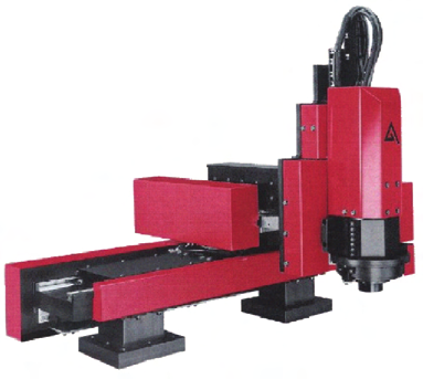
repeatability of 1 µm. A typical exponent of this class of robots is the Sysmelec Autoplace
411 (Fig. 2) (Hesselbach et al., 2005). Another solution for micro assembly robots are
conventional Scara robots in combination with redundant high-precision axes in order to
reach a high resolution. This approach is always combined with additional sensors to
achieve a good repeatability (Höhn, 2001).
Fig. 2. Serial robot Sysmelec Autoplace 411 with Cartesian structure
The development of size-adapted robots is another solution of robots for micro assembly.
Saving costs is only possible by reducing the footprint of an assembly system due to the
demand of a clean room environment for the production of MST products. In recent years,
the reduction of size and costs of micro production systems has been widely discussed in
various papers. Most of these concepts relate to one of the two general groups explained in
the following.
The first group consists of piezo driven, small walking micro robots and handling machines.
These autonomous robots are suitable for positioning small objects such as the MINIMAN
of (Fatikow, 2000), a handling device for samples in a scanning electron microscope. On the
one hand, these micro robots are very promising for new trends such as nano assembly. By
using autonomous robots, difficulties occur regarding the coordination and interaction of
these robots, movement on rough surfaces and energy supply.
The second group describes cost-efficient, size-adapted handling devices, which fill the gap
between piezo driven, small walking micro robots and conventional robots. A possible
solution for this strategy is to determine the highest degree of miniaturization of
conventional robot technology, using innovative, miniaturized machine parts. With these
228
Parallel Manipulators, Towards New Applications
size-adapted handling devices, in the range of several centimeters to a few decimeters,
easily scalable and highly flexible production technology can be designed. Examples of size-
adapted handling devices are the parallel robot structures Delta3 and Sigma 6 from (Clavel
et al., 2005) and the pocket delta from (Coudourey et al., 2006).
This chapter presents a description of four size-adapted robot mechanisms based on parallel
and hybrid structures. For three robot mechanisms, the structures are first designed with
conventional joints and replaced by flexure hinges as ultra-precision machine element later
on.
Furthermore, sensor guided assembly processes of hybrid micro systems are explained on
the basis of one robot structure. Thus, the integration of sensor information into the robot
control as well as the relative sensor guidance applied in the system will be presented. The
positioning uncertainty and the assembly uncertainty of the process are described by means
of an example of an assembly process.
2. Size-adapted parallel and hybrid robot structures
Various size-adapted parallel, parallel hybrid and serial hybrid robots for precision
assembly were developed at the IWF. The main objective to develop size-adapted robot
structures was to adapt the size of the robot cell to the size of the products. At the same time
a good repeatability for highly precise micro assembly processes should be reached through
the development of parallel and hybrid robot structures.
First, a functional model of a planar robot micaboe (see section 2.2) with a parallel structure
and 3 DOF for movement in the x-y plane and 1 DOF as a serial lifting table for movement
in z-direction was implemented. Second, a spatial parallel hybrid robot structure micaboh
(see section 2.3) with 6 DOF was designed. Then, a spatial parallel robot structure, Triglide
(see section 2.4), based on a parallel structure with 3 DOF and one serial rotational axis was
realized.
These three robots were enhanced by integrating flexure hinges (see section 2.1) as ultra-
precision machine elements and named micaboes, micabohs and Triglides. With this machine
elements, the conventional joints of the robot structures are replaced.
Based on the experiences with the above mentioned robot structures, the robot micabof,
which provides 4 DOF for part handling and, as an advanced structure, the micabof2 (see
section 2.5), which provides 4 DOF for part handling and 1 additional DOF for focusing a
vision sensor, were developed as planar serial hybrid robot structures.
2.1 Pseudo-elastic flexure hinges
One way to increase the accuracy of assembly systems is to enhance the positioning
accuracy of the robot itself. Typical problems of parallel structures are the high number of
joints and joints with more than one DOF. Backlash, friction and slip-stick effects in
conventional joints often decrease the overall precision of the robot. As a result of the
natural lack of the above mentioned disadvantages in flexure hinges, replacing conventional
joints by flexure hinges seems to be a promising way to increase the accuracy of robots.
Since flexure hinges gain their mobility exclusively from a deformation of matter, the
attainable angle of rotation is limited. In order to achieve high life cycles of the hinges, the
deformation should remain in the elastic part since plastic deformation normally induces
defects in the material leading to an earlier crack failure (Hesselbach et al., 2004b).
Size-adapted Parallel and Hybrid Parallel Robots for Sensor Guided Micro Assembly
229
The developed flexure hinges consist of a pseudo-elastic shape memory alloy (SMA). This
material offers larger reversible strains than other materials, e.g. spring steel or
thermoplastics, which are commonly used for flexure hinges. Due to the large reversible
strains of SMA, deflections of the hinges of ±30° are possible. This approach offers the
potential to design robots with high accuracy and resolution and with a sufficiently large
workspace for micro assembly tasks (Hesselbach et al., 2004a).
SMA exists in austenite and martensite phases, depending on the temperature or the
applied stress. The temperature and stress values for stable phases mainly depend on the
basic material, their different alloy contents and the thermo-mechanical treatment of the
material. The thermally induced phase transformation of SMA (one way effect) is typically
used in applications in which the SMA device is used as an actuator. We use the stress
induced phase transformation which offers large reversible strains (super-elasticity).
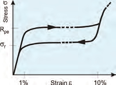
Figure 3 shows a stress-strain diagram of pseudo-elastic SMA loaded with uniaxial tensile
stress. In its initial condition, the material is in its austenitic phase at room temperature.
First, it deforms linear elastic under load. With increasing loads a stress-induced
transformation of austenite into martensite is initiated at the pseudo-yield stress Rpe. The
phase transformation is accompanied by large pseudo-elastic strains εpe with nearly constant
stresses. The pseudo-elastic strain is reverted at a lower stress σr with a stress hysteresis.
Since pseudo-elastic strains are reversible, the specimen completely recovers to its
undeformed shape. These strains are often called pseudo-elastic because the reversible
deformation is caused by a reversible phase transformation and not only due to a translation
of atoms out of their former equilibrium position.
Fig. 3. Stress-strain diagram of shape memory alloy
A pseudo-elastic CuAlNiFe single crystal SMA is used for the design of flexure hinges
because of its superior machinability and extremely large reversible strains up to 17%. The
uniaxial stress-strain diagram of a CuAlNiFe single crystal has two pseudo-elastic stress
plateaus, differing slightly from the example shown in Figure 3, but equivalent in principle.
The first plateau, which is the area of interest, has a yield stress of about Rpe=200 N/mm²
and reversible strains of ε=10%.
A variety of different geometries of flexure hinges are proposed in the literature. They are
designed in monolithic or hybrid processes allowing for up to 3 degrees of freedom (DOF)
(Smith, 2000), (Paros & Weisbord, 1965). When designing flexure hinges for robots
optimisation criteria are high accuracy and a large workspace of the robot. For the three
230
Parallel Manipulators, Towards New Applications
robots micaboes, micabohs and Triglides (described in section 2.2, 2.3 and 2.4) pseudo-elastic
flexure notch hinges with R=15 mm and h=0.15 mm are used. These geometrical dimensions
are an optimum between small kinematic deviations compared to the kinematics of an ideal
rotational joint and small occurring strains. The pseudo-elastic material can be modelled
with a material model by Prandtl-Reuss if the deflection curve is calculated analytically
(Howell & Midha, 1995), (Hesselbach & Raatz, 2000) or with a multilinear elastic material
model using the FEM tool ANSYS. With the chosen geometry and geometrical dimensions
maximal strains are ε=2.1% at deflections of 20° and ε=4.2% at 30°.
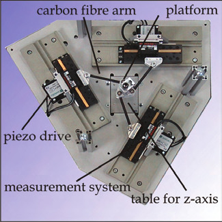
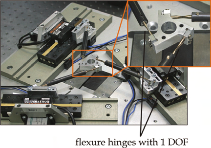
2.2 Planar parallel robot structures micaboe and micaboes with 3 DOF and one serial z-
axis
The planar parallel robot structure micaboe (Fig. 4 left) provides 3 DOF. Three linear drives
move the platform and the gripper with three guiding chains in x-y-direction and enable a
rotation ϕ around the z-axis. The movement in the direction of the z-axis is performed by an
additional elevation platform. The robot is driven by three piezoelectric stick-slip drives
with a smallest step size of 5 nm and is equipped with linear encoders with a resolution of
0.1 µm. First, the pa