2
A 2
2
A 3
(7)
⎪
2
2
2
⎪ =
−
−
+
3
z
l
3
A 1
3
A 2
3
A 3
⎩
where
=
−
β −
β α
11
A
( R r( c
3 s s )) / 2
= −
− α
12
A
3( R rc ) / 2
=
β +
β α
+
13
A
r( s
3 c s ) / 2 z
= −
β +
β α
21
A
R r( c
3 s s ) / 2
=
− α
22
A
3( R rc ) / 2
= −
β −
β α
+
23
A
r( s
3 c s ) / 2 z
= − + β
31
A
R rc
=
32
A
0
= β +
33
A
rs
z
2.2.2 Forward kinematics
The objective of the forward kinematics solution is to define a mapping from the known set
of the actuated inputs to the unknown pose of the output platform. For the architecture with
prismatic actuators, the inputs that are considered known are the lengths of the three
actuator legs 1
z , z 2 and 3
z . The unknown pose of the output platform is described by the
position vector [ o ]' and angles α and β . Because it is very difficult to describe the direct
ℜ
kinematics in closed form for this type of parallel mechanism, the forward kinematics
solution should be obtained by numerical methodology as following:
1. Decide the non-singularity workspace of the mechanism;
2. Give the initial value of direct kinematics solution;
326
Parallel Manipulators, Towards New Applications
3. Calculate the position coordinates of spherical joints, construct the nonlinear
equations set by the geometry constraint relationship of fixed length links;
4. Solve the nonlinear equations set by Quasi-Newton method (Press et al., 1995).
From the Eq. (6), the nonlinear equations are
f ( z,α,β )
2
2
2
2
= l − A −
−
−
=
1
A 2 ( z
A 3)
0
i
i
i
i
i
, ( i = 1, 2, 3 )
(8)
where the direct kinematics solutions are z , α and β .
2.2.3 Velocity equation
Eq. (6) can be differentiated with respect to time to obtain the velocity equation. This leads
to an equation of the form.
J p
=
p
Jqq
(9)
where q is the vector of Cartesian velocities defined as
T
q = ⎡ z,α,β ⎤
⎣
⎦
(10)
and p
is the vector of input velocities defined as
T
p
= [
1
z , z 2, z 2]
(11)
Matrices J
×
p and Jq are the 3
3 forward and inverse Jacobian matrices of the mechanism
and can be expressed as
⎡( −
1
z
1
A 3)/ l
0
0
⎤
⎢
J
0
(
⎥
=
−
p
z 2
2
A 3)/ l
0
⎢
⎥
(12)
⎢
0
0
( −
⎥
⎣
3
z
3
A 3)/ l⎦
⎡( w
v × w
v × w
⎤
1)
(
z
1
1)
(
x
1
1) y
⎢
⎥
J = ⎢( w
v × w
v ×
q
2 )
(
z
2
2 )
(
x
2
w 2) y ⎥
(13)
⎢
⎥
( w
v × w
v ×
⎢⎣ 3)
(
z
3
3)
(
x
3
3
w ) y ⎥⎦
where w
v =
i is the unit vector of
i
L , and i
1
R [ i
A ] . ( w ) is the element of vector w with
ℜ'
i z
i
respect to z axis coordinate, ( v × w )
v ×
v ×
i
i x and (
w )
i
i y are the elements of vector i
wi with
respect to x and y axis coordinates.
2.3 Mechanism accuracy analysis
When the large spherical radio telescope works, the feed system will illuminate a working
area, which is the paraboloid reflector with a three-hundred-meter aperture. The part of
spherical reflector illuminated by the feed is continuously adjusted to fit a paraboloid of
revolution in real-time, synchronous with the motion of the feed while tracking the object to
The Analysis and Application of Parallel Manipulator for Active Reflector of FAST
327
be observed. For the fitting, the spherical surface reflector is divided into some small
elementary units. When the mechanisms drive the reflector units to fit the paraboloid, the
fitting surface of reflector will not match exactly with the nominal paraboloid. Moreover, the
mechanism has error because of the control or dimensional factor. In this section, the
mechanism accuracy is analyzed firstly.
The mechanism accuracy involves the error caused by the actuator input error and the joint
error of the mechanism. The actuator input error is denoted as δ p = [δ z ,δ z ,δ z ]T
1
2
3
and the
T
joint error is denoted as
T
T
18 1
δ e = δ A
δ
×
⎡
B ⎤ ∈
( = 1,....3)
δ
×
B ∈
=
i
i
R
i
⎣
⎦
, where
T
9 1( 1,....3)
i
R
i
includes the joint error on the base platform and the input error δ p = [δ z ,δ z ,δ z ]T
1
2
3
. The
output error is denoted as δ q = [δ z δα δβ ]T
,
,
.
From Eq. (5) and (6), the inverse kinematics equation can be written as
R A
+ ′
o
− B
= L =
1 [ i ]
[ ] [ i]
w
(14)
'
i
il
ℜ
ℜ
ℜ
Differentiating Eq. (14) leads to
δ l = J δ q + J δ
q
e e
(15)
where
T
T
⎡ w R − w
⎤
1
1
1
0
0
0
0
⎢
⎥
T
T
3 18
J = ⎢ 0
0
w R
− w
⎥ ∈
e
2
1
2
0
0
R ×
(16)
⎢
⎥
T
T
⎢ 0
0
0
0
w R
−
3
1
3
w ⎥
⎣
⎦
and δ l = [δ l ,δ l ,δ l ]T δ
1
2
3
, il ( i =1,2,3) is the manufacturing or measuring error of the i-th link.
When Jq is nonsingular in the workspace, Eq. (15) can be rewritten as
1
δ
−
q = J
δ l − J δ
q (
e e )
(17)
3. Fitting accuracy analysis of active reflector
3.1 One dimensional fitting accuracy analysis
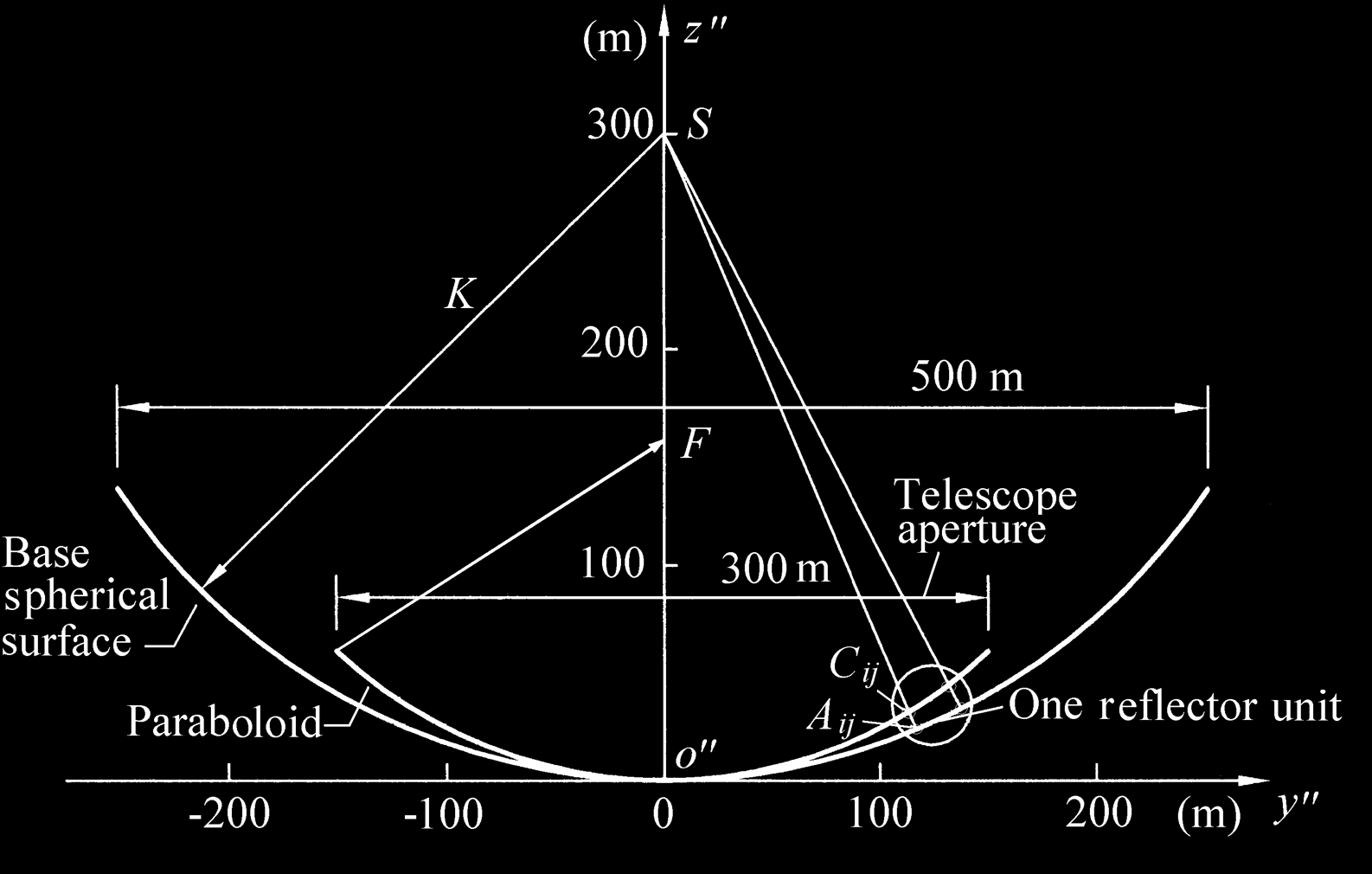
As shown in Fig. 4, the base active reflector of the radio telescope is a spherical surface with
five-hundred-meter aperture, and the working reflector is a paraboloid with a three-
hundred-meter aperture. When it works, the reflector units are driven by the parallel
mechanism from the initial position to the fitting position to fit the paraboloid. Because the
paraboloid is formed by the revolution of parabola, we can analyze the deviation about
spherical surface and paraboloid in the reflector frame ℜ'' : o''− y '' z '' , which is built as
shown in Fig. 4, where the spherical surface and the paraboloid in the frame ℜ'' are circular
arc and parabola, respectively.
328
Parallel Manipulators, Towards New Applications
Fig. 4. Configuration of the active reflector
sl
Ai 3
o′ i
r
A
A
i 2
i 1
M
(a) Initial and fitting position
(b) The A direction view of initial position
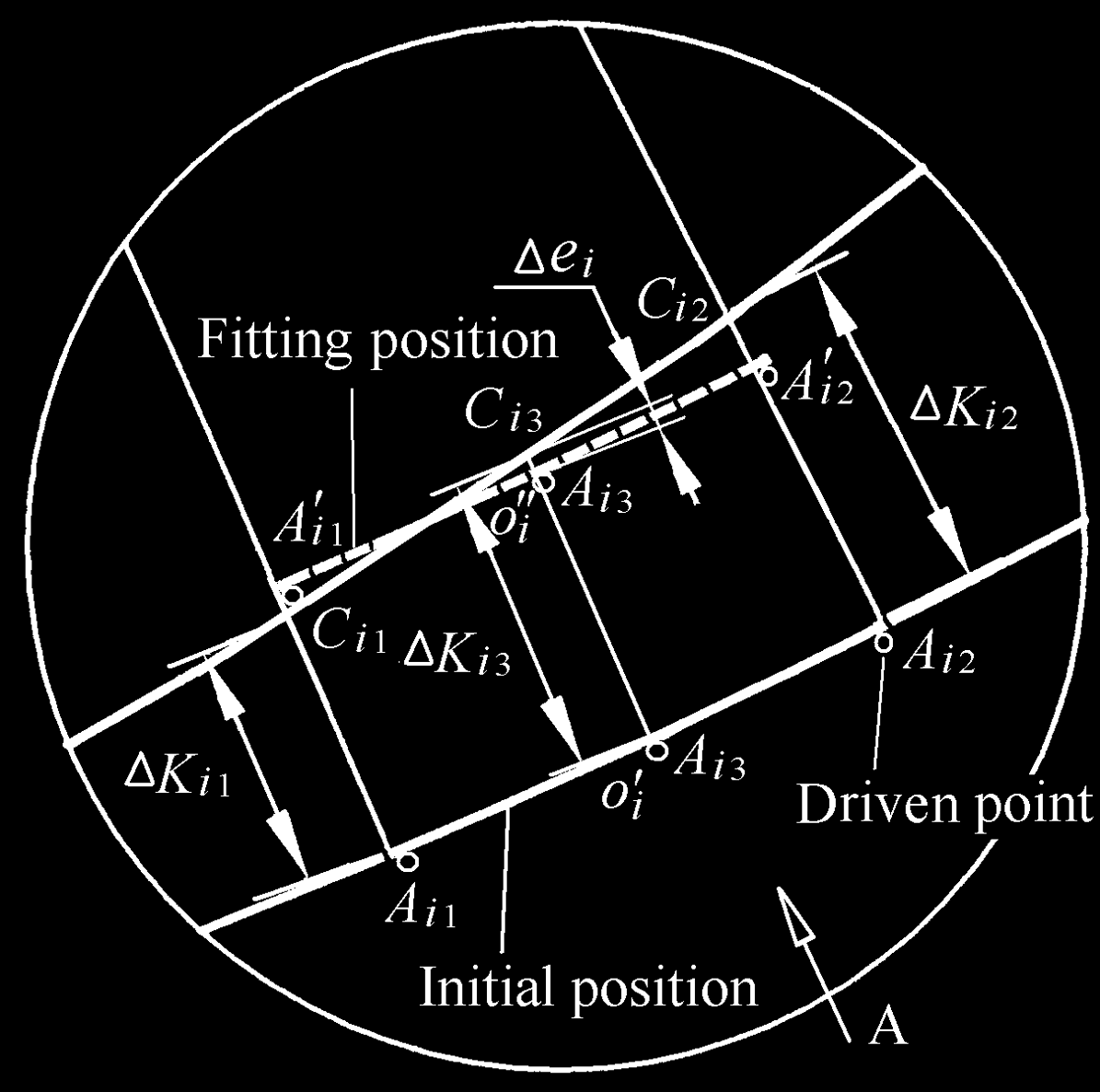
Fig. 5. The i-th reflector unit
Fig. 5 shows one reflector unit which is in the initial position and fitting position,
respectively. The initial position is located at the base spherical reflector surface. The
deviation from the circular arc to the parabola is denoted as K
Δ ij , and symbol i represents
the i-th reflector unit which corresponds to the i-th mechanism. The symbol j ( j = 1,2,3)
represents the supporting point of the movable platform. The explanations of other symbols
used in accuracy analysis are:
ij
A The supporting point while the reflector unit is in the initial position.
ij
A′ The supporting point while the reflector unit is in the fitting position.
ij
C The intersecting points of line
ij
SA and the parabola.
The Analysis and Application of Parallel Manipulator for Active Reflector of FAST
329
i
o′ The refence center in the movable platform while the reflector unit is in the initial
position.
i
o′′ The refence center in the movable platform while the reflector unit is in the fitting
position.
S The center of spherical reflector.
K The radius of spherical reflector.
F The focal point of the paraboloid.
The absolute actuator input of the i-th mechanism is specified as K
Δ ij ( j =1,2,3) , while the i-
th active reflector unit is driven to fit the paraboloid. Obviously, the driven reflector unit
will not match exactly with the nominal paraboloid. In order to evaluate the fitting error, as
shown in Fig. 5,
i
e
Δ is defined as the center points deviation of the i-th reflector unit to the
corresponding paraboloid and
i
e
Δ is equal to io i
C
′ 3 , where the center points deviation ie
Δ
is called as one-dimensional fitting error.
3.1.1 Parabola equation and circle equation
According to the reference (Qiu 1998), the focal length of the parabola is specified as
0.476 K , then the parabola equation can be written as
1
2
z′ =
y′
(18)
4 × 0.467 K
The base spherical surface in reflector coordinate system ℜ'' is a circle. And the circle
equation can be written as
2
2
z′ = K − K − y′
(19)
3.1.2 Actuator input range
The coordinate of the point
ℜ
⎡ A ⎤
ij
A in the frame ′ can be described by the vector ⎣ ij ⎦
ℜ′
( j = 1, 2, 3 ), then
T
⎡ A ⎤ = ⎡ y′ , ′ ⎤
⎣ ij
z
⎦
, ( j = 1,2,3)
(20)
ℜ''
⎣ ij ij ⎦
The equation of straight line
ij
SA can be written as
( z′ − K ) y′
ij
z′′ =
+ K , ( j = 1,2,3)
(21)
′′ ij
y
According to Eqs. (19) and (21), the intersecting point ij
C between line
ij
SA and the circle
can be expressed by vector ⎡ C ⎤
⎣ ij ⎦ , which is
ℜ''
T
⎡ C ⎤ = [ y′ , z′ ]
⎣ ij ⎦
, ( j = 1,2,3)
(22)
ℜ''
cij
cij
330
Parallel Manipulators, Towards New Applications
Actuator input value of the i-th reflector unit can be written as
2
2
K
Δ
= K − SC = K − ( y′ ) + ( K − z′ )
ij
ij
cij
cij
, ( j = 1,2,3)
(23)
3.1.3 One-dimensional fitting error
When actuator input K
Δ ij , ( j =1,2,3) is specified, the fitting error ie
Δ can be reached. The
first step is to calculate the position coordinate [ ′
o ]
T
′ = [ , ]
i
y z in the frame ℜ by the forward
ℜ
ℜ
kinematics solution. The position vector of center point
ℜ
i
o′ in the frame ′ is written as
[ ′ o]′ = [ y′′′ , z′′′ ]T =