be calculated. Firstly, as shown in Fig. 7, one point in parabola is denoted as C ( y′ , ′
C
C
z ) , The
equation of straight line SC can be written as
( z′ − K ) y′
c
z′ =
+ K
(34)
′ c
y
According to Eqs. (33) and (34), the intersecting point A between line SC and the circle
arc A′ ′ ′
′ ′
1
i
i
A 3 i
A 2 can be expressed by A( y ,
A zA ) . The fitting error of given point is expressed as
2
2
e
Δ ′ = SA − SC = ( y′ − y′ ) + ( z′ − z′ )
y
C
A
C
A
(35)
The area of the closed region can be written as
y′
Ci 2
=
Δ
′
i
Se
e
∫
y′ dy
(36)
y′ Ci 1
The Analysis and Application of Parallel Manipulator for Active Reflector of FAST
333
which is the two-dimensional fitting error of the i-th reflector unit. Then the average error of
the two-dimensional fitting error is defined as
Se
i
=
i
Qe
(37)
′ − ′
Ci
y 2 y 1
Ci
In the end, the two-dimensional root-mean-square (RMS) fitting error of the paraboloid
reflector with three-hundred-meter aperture is defined as
n
2
∑ i
Qe
i 1
=
=
Qe
R
(38)
n
where n is the number of reflector units that consist of three-hundred meter aperture
parabola.
3.2.3 Two-dimensional accuracy synthesis analysis
The two-dimensional accuracy synthesis analysis is defined as the composition RMS error
that caused by the mechanism actuator input error and the two-dimensional fitting error,
which is denoted as Qe
R′ . The Eqs. (28), (37) and (38) can be used to calculate the two-
dimensional composition RMS fitting error Qe
R′ .
3.2.4 Simulation example
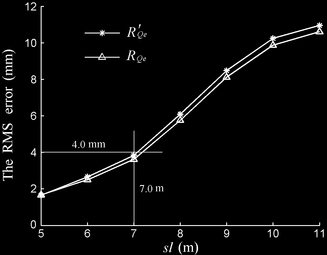
The two-dimensional RMS error and composition RMS fitting error are shown in Fig. 8,
where all the dimensional design parameters are the same as the specified parameters in
section 3.1.5. Comparing the Fig. 8 and Fig. 7, we can know although both the one-
dimensional and two-dimensional RMS fitting error increase while the side length of
reflector unit increases, the two-dimensional RMS error is larger than one-dimensional RMS
error.
Fig. 8. The two-dimensional RMS fitting error of active reflector
334
Parallel Manipulators, Towards New Applications
According to the fitting error requirement given by reference (Qiu, 1998), when the highest
working frequency of the radio telescope is 5GHz, the reflector RMS fitting error should be
less than 3.75 mm. Now, we can decide the dimensional parameters and guarantee the
implementation of the working frequency by the one-dimensional or two-dimensional RMS
fitting error curves. For example, according to the Fig. 7, if the side length of reflector unit is
specified as 7.5m, the specified dimension of reflector units can satisfy the requirement of
5GHz work frequency. However, as shown in Fig. 8, if the two-dimensional RMS fitting
error is used to evaluate the fitting accuracy, the side length of reflector unit should less than
7.0m for satisfying the requirement of 5GHz work frequency.
4. The error kinematics of 3-PRS mechanism
3-PRS mechanism has less chians which reduces its cost. The kinematics of 3-PRS
mechanism has been fully analyzed (Carretero et al., 1997; Tsai & Shiau, 2003). Yet, when the
mechanical manufacturing and assembling errors are brought into the model, kinematic
analysis will become complicated. Therefore, analysis on parasitic motion and accuracy
should be made to guarantee the application of 3-PRS mechanism as reflector unit
supporting mechanism.
4.1 Kinematic modeling with errors
The magnitude of the reflector driving machine is always at meter, so input error, length
error of the legs and location error of the spherical joint have little influence on motion error
of the moving platform. On the other hand, the location and angle error of the rotational
joint, which will be extended by the legs, will mix with parasitic motion so as to greatly
affect the motion. Therefore, we introduces angle error of the rotational axis and location
error of the joint point in the rotational joint as the main error resources in order to analyze
kinematics of 3-PRS error model.
z′
Moving platform
y′
i
A
o′
x′
i
P
i
P
H
P′ i
Δ P
Δ
i
B
B′
i
i
B
i z
P′
y
B′ i
i
x
o
i
B
Base platform
(a) (b)
Fig. 9. Kinematic error model of 3-PRS mechanism
In the error model representation of 3-PRS mechanism, as shown in Fig. 9(a), i
P is ideal
axis vector of the rotational joint, and P′ i is actual axis vector with angle error. Similarly, i
B
The Analysis and Application of Parallel Manipulator for Active Reflector of FAST
335
is ideal vector of the rotational joint point, whereas B′ i is actual joint point vector with
location error. Both P′
B′
i and
i include three direction errors separately along x , y , and z
axis, which means that there are six errors in each leg, as shown in Fig. 9(b), in which two-
dot chain line represents ideal rotational joint and real line represents actual one.
The location error vector of the rotational joint is defined as
T
Δ B = ⎡Δ
Δ
Δ ⎤
i
⎣ i
b x
i
b y
i
b z ⎦
The angle error vector of the rotational joint is defined as
T
Δ P = ⎡Δ
Δ
Δ ⎤
i
⎣ i
p x
i
p y
i
p z ⎦
Then we can find
B′ = B + Δ
i
i
i
B
(39)
P′ = P + Δ
i
i
i
P
(40)
The three components of the vector Δ
Δ
i
B are independent while those of the vector
i
P are
not since the error on the direction can be given through two parameters only. So the
relationship between the components of the vector Δ
P + Δ P =
i
P can be determined by ||
|| 1
i
i
,
where
'
|| P || ||
= P ||= 1
i
i
are unit direction vectors. Thus, error resources are appropriately
introduced and error modeling of 3-PRS mechanism is completed.
4.2 Inverse kinematics
The coordinate axes of the inertial frame fixed on the base platform are denoted by
ℜ : o − xyz while those of the moving frame fixed on the moving platform are denoted by
′
ℜ : o′ − x y
′ z′′ (see Fig. 9). In order to simplify the kinematic model, the origin of the inertial
frame is located on the center of the base platform and x axis of the inertial frame points to
one of the spherical joint on the base platform. The y axis is also on the plane of the base
platform while z axis points upward forming a right-handed orthogonal frame. The
coordinate axes of the moving frame are also located on the moving platform in the same
way. The rotation matrix from the coordinate axes of the moving platform to those of the
base platform is denoted by R which is expressed as
⎡ cφ cθ cφ sθ sψ - sφ cψ
cφ sθ cψ + sφ cψ ⎤
⎢
R
sφ cθ sφ sθ sψ
cφ cψ
sφ sθ cψ - cφ sψ ⎥
=
+
⎢
⎥
⎢ - sθ
cθ sψ
cθ cψ
⎥
⎣
⎦
where ψ , θ , and φ are variables which orderly specify the rotations around the x , y ,
and z axis, and s represents sin, while c represents cos.
[ H] = [
]T
x y z is the vector from the origin of the inertial frame to the origin of the
ℜ
moving frame expressed in the inertial frame.
336
Parallel Manipulators, Towards New Applications
[ iB] is the vector
ℜ
i
B expressed in the inertial frame.
[ B′
B′
i ] is the vector
expressed in the inertial frame.
ℜ
i
[ P ] = [ p p
]T is the vector
ℜ
1
2
0
i
i
i
i
P expressed in the inertial frame.
[ P′
P′
i ] is the vector
expressed in the inertial frame.
ℜ
i
[ A ] = [ a a
is the vector from the origin of the moving frame to the i-th upper
ℜ′
]T
1
2
0
i
i
i
attachment point expressed in the moving frame.
[ iL] is the vector from the rotational point to the upper attachment point of the i-th leg. It
ℜ
should be noted that [ L
=
i ]
i
l is constant for each leg.
ℜ
T
S = ( 1
S , S 2, S 3) is the set of actuated joint variable of the 3-PRS mechanism which is the
height of the rotational joint point. We can get
[ B =
i ]
[ ib
i
b
S
ℜ
i ]T
1
2
The inverse kinematic problem is supposed to determine the value of the actuated variables
for a known position and orientation of the end-effector, that is: S = f ( x, y, z,ψ ,θ,φ) .
In those six variables, the known numbers are three desired motions which include z , ψ ,
and θ , while the unknown numbers are three parasitic motions which include x , y , and
φ . The parasitic motions are determined by the target motions, that is: ( x, y,φ) = g( z,ψ ,θ ) .
The structure of mechanical joint leads to two geometrical constraints which are rotation
constraint and length limitation of the leg.
(a) The rotation constraint
Each attachment point of the moving platform should be restricted in the rotation plane
formed by the wheeling leg. The constraint equations are
[ P ]T
′ ( R[ A ] + [ H] ) + = 0
i
, i = 1,2,3
(41)
ℜ
i ℜ
ℜ
i
C
′
where i
C is a constant of the rotation plane and determined by the following equation
[ P ]T
′ [ B′] + = 0
i
i
i
C
, i = 1,2,3
(42)
ℜ
ℜ
Substituting Eq. (39) into Eq. (42)
[ P ] +[Δ P ] T
(
) [( B ] + [Δ B ] ) +
= 0
i
i
i
i
i
C
(43)
ℜ
ℜ
ℜ
ℜ
Expressing with the elements of those vectors, we get
m S + C + n = 0
i i
i
i
(44)
where
= Δ
=
+
+ Δ
+ Δ
+
Δ
+
Δ
+ Δ Δ
+ Δ Δ
+ Δ Δ
i
m
i
p z , i
n
p 1 ib 1 i
i
p 2 ib 2
i
p xb 1 i
iy
p ib 2 p 1 i ix
b
i
p 2 iby
i
p x ibx
i
p y iby
i
p z ibz
Substituting Eq. (40) into Eq. (41)
The Analysis and Application of Parallel Manipulator for Active Reflector of FAST
337
[ P ] +[Δ P ] T
(
) ( R[ A ] + [ H ] ) +
= 0
i
(45)
ℜ
i ℜ
i ℜ
ℜ
i
C
′
Expressing with the elements of those vectors, we get
f cφ + g sφ + h x + k y + j + C = 0
i
i
i
i
i
i
(46)
where
f =
θ +
θ ψ +
ψ + Δ
θ +
Δ
θ ψ +
Δ
ψ
i
a 1 ip 1 ic
i
a 2 p 1 is s
i
a 2 i
p 2 c
a 1 i i
p xc
i
a 2 i
p xs s
i
a 2 i
p yc
g = −
ψ +
θ +
θ ψ −
Δ
ψ + Δ
θ +
Δ
θ ψ
i
i