International Conference on Robotics & Automation, pp. 2448-2453, Korea, May. 2001,
IEEE, Seoul
Wang, J.-S. & Tang, X.-Q. (2003). Analysis and dimensional design of a novel hybrid
machine tool. I nternational Journal of Machine Tools and Manufacture, Vol. 43, No. 7,
pp. 647-655
Wang, Q.-M.; Tang, X.-Q.; Zhu, L.-C. et al. (2006). Patent: Co-driving Array Parallel
Mechanism for Large Radio Telescope, 200610011941.0
16
A Reconfigurable Mobile Robots System
Based on Parallel Mechanism
Wei Wang1, Houxiang Zhang2, Guanghua Zong1 and Zhicheng Deng1
1 Beijing University of Aeronautics and Astronautics ,
2 University of Hamburg,
1 China,
2 Germany
1. Introduction
Reconfigurable robots consist of many modules which are able to change the way they are
connected. As a result, these robots have the capability of adopting different configurations
to match various tasks and suit complex environments. For mobile robots, the
reconfiguration is a very powerful ability in some tasks which are difficult for a fixed-shape
robot and during which robots have to confront unstructured environments (Granosik et al.
2005; Castano et al. 2000), e.g. navigation in rugged terrain. The basic requirement for this
kind of robotic system is the extraordinary motion capabilities.
In recent years considerable progress has been made in the field of reconfigurable modular
robotic systems, which usually comprise three or more rigid segments that are connected by
special joints (Rus, D. and Vona, M. 2000). One group of the reconfigurable robots featuring
in interconnected joint modules realizes the locomotion by virtue of the structure transform
performed by the cooperative movements and docking/undocking actions of the modules
(Suzuki et al. 2007; Kamimura et al. 2005; Shen et al. 2002; Suzuki et al. 2006; Vassilvitskii et
al. 2002). Because the modules in these robots are not able to move independently and the
possible structures of the robot are limited, these kinds of robots are not suitable for the field
tasks.
The other kind of reconfigurable robots being composed of independently movable modules
is more suitable for the field environment. The first prototype (Hirose et al. 1990) with
powered wheels was designed by Hirose and Morishima in 1990, which consists several
vertical cylindrical segments. The robot looks like a train, however with a weight over 300
kg it is too heavy. Klaassen developed a mobile robot with six active segments and a head
for the inspection of sewage pipes (Klaassen et al. 1999). There are twelve wheels on each
module to provide the driving force. Mark Yim proposed another reconfigurable robot
PolyBot which is able to optimize the way its parts are connected to fit the specific task (Yim
et al. 2000). PolyBot adopts its shape to become a rolling type for passing over flat terrain, an
earthworm type to move in a narrow space and a spider type to stride over uncertain hilly
terrain.
The application of powered tracks to field robots enriches their configurations and improves
the adaptability to the environments. A serpentine robot from Takayama and Hirose
348
Parallel Manipulators, Towards New Applications
consists of three segments. Each segment is driven by a pair of tracks, but all tracks are
powered simultaneously by a single motor located in the centre segment (Takayama et al.,
2000). The special ability of adapting to irregular terrain is passive and provided by springs.
The OmniTread serpentine robot (Granosik et al. 2005) for industrial inspection and
surveillance was developed by Grzegorz Granosik in 2004. Optimal active joints are
actuated by pneumatic cylinders in order to compromise the strength and compliance.
However, the known robots usually have few configurations due to relatively simple
docking and pose-adjusting mechanisms. For example, the Millibot Train robot consists of
seven compact segments, which can connect by couplers with one DOF (Brown et al. 2002).
A reconfigurable mobile robot designed by M. Park is not able to change its configuration
actively at all (Park et al. 2004). The robot from Université Libre de Bruxelles has a one-DOF
pose-adjusting mechanism and one coupler to change the configuration between the
neighboring modules as well (Sahin et al. 2002).
From the mechanical point of view, the reconfiguration mechanism applied to mobile robot
is composed of the posture-adjusting and connecting mechanism, and the most important
technology is how to construct a posture-adjusting mechanism with large workspace and
high driving ability in a limited robot body. However, in complex field terrain, the fact that
the existing reconfigurable mobile robots can only assume limited configurations due to
relatively simple posture-adjusting is a ubiquitous deficiency.
The project presented in this chapter aims at developing a reconfigurable mobile multi-robot
platform made highly flexible and robust by its three-DOF posture-adjusting ability. The
key object of the project is to develop a new posture-adjusting mechanism featuring in
compact structure, large workspace and powerful driving ability. As a secondary object, the
project has developed an effective connecting mechanism aligned to flat terrain and
synthesized it with the posture-adjusting mechanism. The locomotion abilities of the system
are expected to be as follows.
1. The single robots in the system have an independent omni-directional locomotion
ability equivalent to that of a normal outdoor mobile robot.
2. Due to the posture-adjusting mechanism, which enables the robots to drive very well
and to operate in a large workspace, the robots can adjust the posture of their partners.
3. The connecting mechanism tolerating large posture deviation in flat terrain can link two
robots in a locked connection and transit large forces and torques between them.
4. Compared with a single robot, the connected robots are able to perform more
demanding locomotion activities, such as stepping over high obstacles, crossing wide
grooves, passing through narrow barriers and self-recovering from invalid postures
and other actions which are impossible for a single robot.
To reach the above targets, a novel reconfigurable mobile robot system JL-1 based on a serial
and parallel active spherical mechanism and a conic self-aligning connecting mechanism has
been developed. This system is composed of three robot modules which are able to not only
move independently, but also to connect to form a chain-structured group capable of
reconfiguration. On flat terrain, each module of JL-1 can corporate with each other by
exchanging information to keep up its high efficiency; while on rugged terrain, the modules
can actively adopt a reconfigurable chain structure to cope with the cragged landforms
which will be a nightmare for a single robot (Zhang et al. 2006; Wang et al. 2006).
In the chapter, after giving an overview of JL-1, the discussion focuses on some special
locomotion capabilities of it. Then the related kinematics analysis of the serial and parallel
A Reconfigurable Mobile Robots System Based on Parallel Mechanism
349
mechanism is discussed thoroughly as well as the theory of the connecting mechanism.
Based on the discussion, the mechanical realization of JL-1 is introduced in detail. The
prototype shows the advantage of the parallel mechanism in realizing powerful driving
force in a relative small size. In the end, a series of successful on-site tests, such as crossing
high vertical obstacles, connecting action and getting self-recovery when the robot is upside-
down, is presented to confirm the above principles and the locomotion abilities of JL-1.
2. Overview of the reconfigurable JL-I
2.1 Mechanical model of JL-1
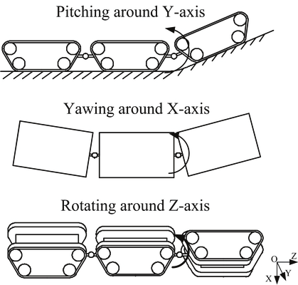
Fig. 1. Adapting to terrains by pitching, yawing and rotating
By virtue of three uniform modules being capable of docking with each other, JL-I has
various moving modes which enable JL-1 to move in almost all kinds of rough terrains. The
principle of terrain adaptability is shown in Fig. 1. In connected state, JL-I can change its
posture by pitching around the Y axis, yawing around the X axis and rotating around the Z
axis. JL-1 is endowed with the abilities of adopting optimized configurations to negotiate
difficult terrains or splitting into several small units to perform tasks simultaneously, by the
three DOF active spherical joints between the modules and the docking mechanism being
capable of self-aligning within certain lateral and directional offsets.
In JL-1, the yawing and pitching movements are achieved by a parallel mechanism. The
third rotation DOF around the joint’s Z axis is achieved by a serial mechanism. There are
two reasons for using the serial and parallel mechanisms for JL-1. Firstly, the JL-I robot can
be made lightweight and dexterous while allowing for a larger payload. Secondly, the
advantages of the high rigidity of a parallel mechanism and the extended workspace of a
serial mechanism can be combined, thus improving the flexibility of the robotic system.
2.2 Locomotion capabilities
It can be easily imagined that the locomotion abilities of JL-1 will be enhanced when it is in
connected state, such as climbing up higher steps, spanning wider ditch and stepping up
stairs. Furthermore, JL-1 is capable of some novel actions, which will be required in outdoor
environment, e.g. self-recovery and passing through a narrow fence.
350
Parallel Manipulators, Towards New Applications
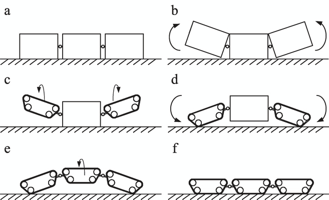
2.2.1 90° self-recovery
It is possible for the robot to implement a 90° recovering movement by adopting the proper
configuration sequence as shown in Fig. 2.
a) The robot is lying on its side
b) The first module and the last module are yawing up around the X axes of the active
joints.
c) Then the first module and the last module rotate 90° around the Z axes.
d) After that, they are pitching down around the Y axes of the active joints until they
attach to the ground in order to raise the middle module up.
e) The middle module rotates around the Z axis until it is parallel to the ground.
f) In the end, the module is pitching down around the Y axes of the active joints until all
three modules attach to the ground together. The robot is now in its home state again,
and the process of 90° Self-recovery is over.
Fig. 2. 90° recovering movement
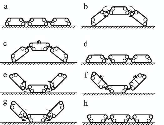
2.2.2 180° Self-recovery
It is also possible for the robot to tip over and realize the 180° recovery movement as shown
in Fig. 3.
Fig. 3. 180° recovering movement
A Reconfigurable Mobile Robots System Based on Parallel Mechanism
351
a) The robot is in its home state.
b) The first and the last modules are pitching down around the Y axes of the active joints
until the middle module is in the air.
c) The middle module rotates 180° according to the Z axis.
d) The first module and the last module are pitching down around the Y axes of the active
joints until the middle module attaches to the ground.
e) The first module and the last module are pitching up around the Y axes of the active
joints again.
f) The first module and the last module are rotating 180° around the Z axes of the active
joints.
g) Then the first module and the last module are pitching down around the Y axes of the
active joints again until all three modules attach to the ground.
h) The process of 180° Self-recovery is over.
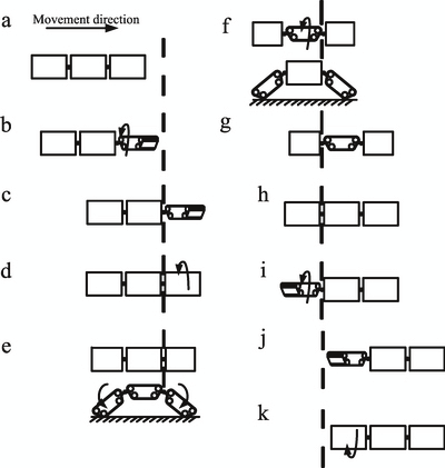
2.2.3 Crossing a narrow fence
As shown in Fig. 4, the train configuration robot is able to cross a fence narrower than the
width of its modules.
a) The robot is in its home state, and the sensor detects the fence in the moving direction.
b) The robot stops before the fence, and then the first module pitches up around the Y axis
and then rotates 90° according to the Z axis.
c) The crossing movement does not stop until the first module passes through the fence.
d) The first module rotates and pitches to get back into the home state, and then the three
modules attach to the ground together again.
The following steps (e) to (k) of the second and third modules are similar to those of the first
one. The process will be achieved until the robot crosses the fence entirely. In order to show
the principle clearly, the lateral views of steps (e) and (f) are also given.
Fig. 4. The sequence of crossing a narrow fence
352
Parallel Manipulators, Towards New Applications
3. Kinematics analysis of the active spherical joint
As described above, the robot’s reconfiguring abilities are achieved by the motion of the 3
DOF active spherical joints. Two of the DOF achieved by the parallel mechanism are yawing
and pitching around the joint’s X and Y axes respectively. The third rotation DOF around
the joint’s Z axis is achieved by the serial mechanism.
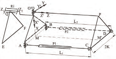
Fig. 5. The kinematics model of the active spherical joint
To demonstrate the reconfiguring possibility, the kinematics analysis of two connected
modules should be studied first. Fig. 5 shows the kinematics model of the joint between two
modules. Where OXYZ is the world coordinate fixed at the plane QEF which represents the
front unmovable module during the reconfiguration. The origin is located at the universal
joint O, the Z-axis coincides with the axis of the serial mechanism and the X-axis points to
the middle point of line AB. Another reference coordinate O’X’Y’Z’ is fixed at triangular
prism OABPCD which represents the back moveable module. The O’X’Y’Z’ is coincident
with the OXYZ when the spherical joint is in its home state. Equations (1) and (2) are
satisfied due to the mechanical constraints. QF is perpendicular and equal to QE.
QEF//OAB//PCD
(1)
QEF=OAB=PCD
(2)
The required orientation for the reference frame O’X’Y’Z’ on the back module is achieved by
a rotation of θz, a pitching angle θy and a yawing angle θx according to the relative axes.
From the mechanical point of view, actually the pitching and yawing motions are realized
by the outstretching and returning movement of the L 1, L 2 of the parallel mechanism, and
the rotation of θz is actuated by the serial mechanism. The freedom of the reconfiguring
movement is three and can be described with the generalized coordinate θ (3). The joint
variants of the movement are named q, described as (4).
θ= [θx, θy, θz]T
(3)
q= [L1, L2, θz]T
(4)
The purpose of the kinematics analysis is to deduce the relationship between q and θ. In Fig.
10, the points A, B, C, D are described as (5) in the OXYZ coordinate.
⎡ K ⎤
⎡ K ⎤
⎡ K ⎤
⎡ K ⎤
⎢
⎥
⎢ ⎥
⎢
⎥
⎢ ⎥
A = ⎢− K⎥ B = ⎢ K⎥ C = ⎢− K⎥ D = ⎢ K⎥
⎢0 ⎥
⎣
⎦
⎢0 ⎥
⎣ ⎦
⎢ L ⎥
⎣
⎦
⎢ L ⎥
⎣ ⎦
(5)
A Reconfigurable Mobile Robots System Based on Parallel Mechanism
353
The homogeneous transformation matrix [ T] from the world coordinate OXYZ to the
coordinate O’X’Y’Z’ is described as (6).
⎡ cθ
0 sθ ⎤ ⎡1
0
0 ⎤ cθ
sθ
y
y
⎡
−
0
z
z
⎤
⎢
⎥ ⎢
⎥ ⎢
⎥
T = Rot( Y ) Rot( X ) Rot( Z) =
0
1
0 ⋅ 0 cθ
− s x
θ ⋅
⎢
⎥ ⎢
sθ
cθ
x
⎥ ⎢
0
z
z
⎥
⎢− θ
θ ⎥ ⎢
θ
θ ⎥
s
0 c
0 s
c
⎢ 0
0
1⎥
⎣
y
y ⎦ ⎣
x
y ⎦ ⎣
⎦
(6)
After the reconfiguring movement, A, B, C, and D are changed to new positions described as
A 1, B 1, C 1, and D 1. The Cartesian coordinates of the new points can be expressed as (7) and
(8).
[ A
B ] = Rot( Z )[ A
B]
1
1
(7)
[ C D
1
1 ] = T[ C
]
D
(8)
There are some constraints to the mechanical structure, as shown in (9) and (10). The lengths
of the link L 1 and L 2 are equal to the distance between C 1 A 1 and D 1 B 1 respectively.
L = C − A
1
1
1
(9)
L = D − B
2
1
1
(10)
All these results are inserted into (9) and (10), then the kinematics expression results from
them.
2
L = ( K ( cθ cθ + sθ sθ sθ ) −
1
y
z
x
y
z
K (− sθ cθ + sθ sθ cθ ) +
z
y
x
y
z
2
Lcθ sθ − Kcθ − Ksθ ) +
x
y
z
z
2
( K ( cθ sθ ) − K( cθ cθ ) − Lsθ − Ksθ + Kcθ )
x
z
x
z
x
z
z
+ ( K(− sθ cθ + sθ cθ sθ ) −
y
z
x
y
z
2
θ θ + θ θ θ + θ θ
K ( s s
s c c ) Lc c )
y
z
x
y
z
x
y
(11)
2
L
= ( K( cθ cθ + sθ sθ sθ ) +
2
y
z
x
y
z
K (− sθ cθ + sθ sθ cθ ) +
z
y
x
y
z
2
Lcθ sθ − Kcθ + Ksθ ) +
x
y
Z
Z
2
( K ( cθ sθ ) + K( cθ