Hybrid Parallel Robot for the
Assembling of ITER
Huapeng Wu, Heikki Handroos and Pekka Pessi
Lappeenranta University of Technology
Finland
1. Introduction
The international thermonuclear experimental reactor (ITER) is a joint international research
and development project that aims to demonstrate the scientific and technical feasibility of
fusion power. The reactor tokomak (vacuum vessel) is made of stainless steel, and contains
nine sectors welded together; each sector has about the size of 10 meter high and 6 meter
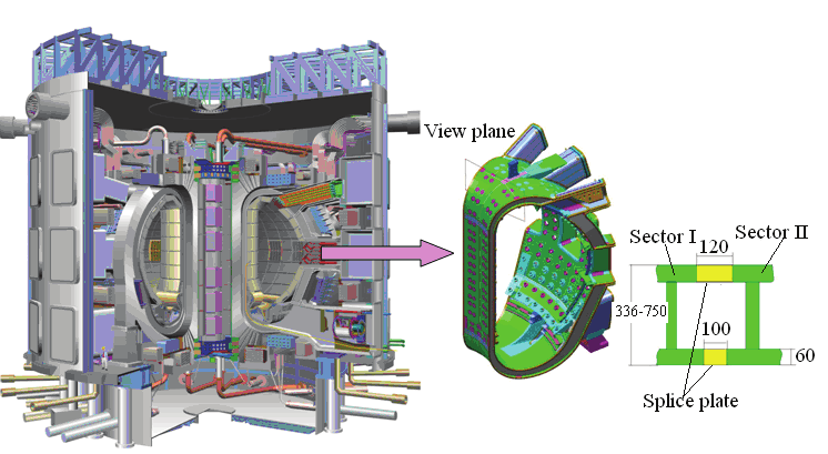
wide. The sectors of ITER vacuum vessel (VV) (Fig. 1) require more stringent tolerance
(±5mm) than normally expected for the size of the structure involved. The walls (inner wall
and outer wall) of ITER sectors are of 60mm thick and are joined by high quality leak tight
welds. In addition to the initial vacuum vessel assembly, the sectors may have to be
replaced for repair. Meanwhile, the machining operations and lifting of a possible e-beam
gun column system require extreme stiffness property and good accuracy for a machine
tool. The payload to weight ratio also has to be significantly better than it is in the
commercial industrial robots.
The conventional robots, providing a high nominal payload, are lack of stiffness and
accuracy in such machining condition. Since commercially available machines capable of
handling large payloads require floor mounting and their workspaces are insufficient for
reaching the cross section at a single mounting position, a special robot is needed. Parallel
robots have high stiffness, high dynamic performance and good payload to weight ratio in
comparison with the conventional serial robots. Stewart [1] presented the novel idea of six-
degree-of-freedom parallel robot in 1960’s. A remarkable number of research articles and
books about parallel manipulators have been published during the last two decades. There
are also a number of successful industrial applications developed [2], [3], [4], [7]. The
parallel manipulators have many potential advantages compared with the conventional
serial link manipulators. Parallel manipulators are closed-loop mechanism presenting good
performances in terms of accuracy, rigidity, high speed, and ability to handle large loads.
They are becoming popular in applications such as machining, welding, assembly, flight
and vehicle simulators, mining machines, and pointing devices [2], [3], [4], [7]. The most
important drawback of parallel robots is the small workspace, which can be made larger by
adding additional serial axes in the robot.
For the assembly of the ITER vacuum vessel sector, the precise positioning of welding end-
effectors at some distance in a confined space from the available supports will be required,
364
Parallel Manipulators, Towards New Applications
while it is not possible using conventional machines or robots. The parallel robot presented
in this paper is able to carry out welding and machining processes from inside the ITER
vacuum vessel, consisting of a six degree-of-freedom parallel mechanism mounted on a
carriage driven by electric motor/gearbox on a rack. The robot carries both welding gun
(such as a TIG, hybrid laser or e-beam welding gun to weld the inner and outer walls of the
ITER vacuum vessel sectors) and machining tools (to cut and mill the walls with necessary
accuracy). It can also carry other heavy tools and parts to a required position inside the
vacuum vessel.
The robot offers not only a device but also a methodology for assembling and repairing VV.
For assembling, an on-line six-degree-of-freedom-seam-finding algorithm has been
developed. The algorithm enables the robot to find welding seam automatically in a very
complex environment. For machining, the multi flexible machining processes carried out
automatically by the robot have also been investigated, including edge cutting, smoothing,
and defect point milling. The kinematic design of the robot has been optimised for the ITER
access and a hydraulically actuated prototype has been built. Finally the experimental
results are presented and discussed. The earlier development phases of the robot are
presented in [8] and [9].
2. Structure of VV and assembling process
The inner and outer walls of the VV of ITER are made of 60mm-thick stainless steel 316L
and are welded together through an intermediate, so-called “splice plate”, inserted between
the sectors to be joined. The splice plates have two important functions: ( i) to allow access to
bolt together the thermal shield between the VV and coils; and ( ii) to compensate the
mismatch between adjacent sectors to give a good fit-up of the sector-sector butt weld. The
robot’s end-effector will have to pass through the inner wall splice plates opening to reach
the outer wall. As shown in Fig.1, the assembly and repairing processes have to be carried
out from inside the vacuum vessel.
Fig.1 ITER and VV sectors to be welded
Hybrid Parallel Robot for the Assembling of ITER
365
The assembly or repair will be performed according to four phases: cutting, edge machining
and smoothing, welding, and non-destructive tests (NDT) control. The robot will carry out
welding, machining, and inspecting inside the VV. The maximum robot force arises from
cutting. It can be up to 3kN.
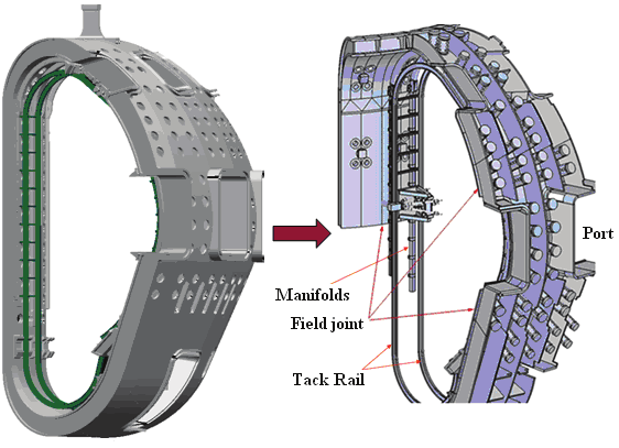
Fig.2 The track rail mounted inside VV and robot on the track
In order that the robot can operate in the cross section of the vessel, a track is assembled
inside the sector. The track has a rack on one side of the rail and it is supported by manifolds
and beams (shown in Fig. 2). The robot driven on the rail carries out welding or machining
along the edge of the sector. After finishing the assembly of two sectors, the robot has to be
moved to the next sector where there is also a track assembled. After finishing the assembly
of all the sectors, the robot can be taken out via the port of VV.
3. Kinematics of parallel robot
3.1 Structure of parallel robot
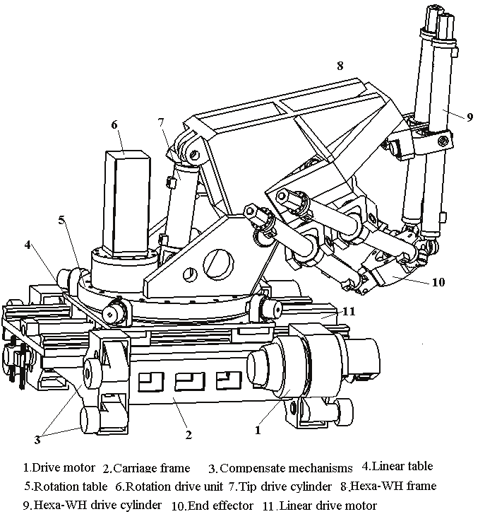
The proposed parallel robot has ten degrees of freedom (Fig. 3). It consists of two relatively
independent sub-structures: ( i) carriage, which provides four additional degrees of freedom,
i.e., rotation, linear motion, tilt rotation and tracking motion, and these four degrees are
added to enlarge the workspace and to offer high mobility; and ( ii) the Hexa-WH parallel
mechanism driven by six hydraulic cylinders contributes six degrees of freedom for the end-
effector. Thus the robot is a hybrid redundant manipulator with four extra degrees of
freedom provided by serial kinematic links.
a). Carriage mechanism
The carriage mainly consists of 5 units. i) Carriage frame: The carriage frame is a complex
structure welded by multi-steel-plates, and it is able to carry high payload and offers
enough room to maintain mechanisms. Stiffness and weight are the most important
considerations in the design, and they have been optimized to achieve necessary stiffness
366
Parallel Manipulators, Towards New Applications
with light weight. ii) Tracking drive unit: The tracking drive unit consists of electric motor,
reduction unit CYCLO, V-shape bearing, and driving gear. The electric servo motor with
Fig. 3 Parallel robot
position feedback controller offers the high accurate motion. In order to output large torque
to drive the heavy mass and payload, the reduction unit CYCLO is added to the motor
to reduce speed and to transmit high torque to the driving gear. Two V-shaped wheels keep
the carriage on the tracking rail at right position to avoid the cross motion. Two drive units
are used in the carriage to offer enough torque in order to drive the robot and payload
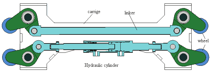
around inside the VV. iii) Compensation mechanism: The compensation system is an important
unit that limits the backlash caused by the inaccurate assembling of the tracking rail and
compensates the distance changing between the wheels in bending area. As the shape of the
VV is very complicated, it is difficult to keep the tracking rails lying on the VV surface in the
accurate position. The position tolerance can be up to ±2mm. The distance of the coupled
wheels has to be adjusted to follow the changes of the rail, and all the wheels must touch the
parallel rails with certain force during motion; hence an adaptive distance compensation
system is needed and it should be able to undertake the summed weight of the robot and
the payload, when the robot is upside down at the top position insider VV. Since the total
Hybrid Parallel Robot for the Assembling of ITER
367
payload is very heavy, a hydraulic cylinder is applied to justify the compensation force
according to the position where the robot is located. Fig. 4 shows the compensation system,
where the upside is the tolerance adaptive mechanism that passively follows the changes of
track rail and the downside is the hydraulic distance compensation system that ensures a
constant force is applied to the rails. iv) Linear drive unit: The linear drive unit enlarges the
workspace of the robot, and consists of five parts: ball screw drive unit, servo motor, rails,
linear bearings, and a table. Two parallel rails are fixed on the carriage frame to offer the
motion crossing the frame and to extend the distance of the robot in direction Y. In direction
Y, the distance from the inner board to the outer board can be 900mm in one VV sector, i.e.,
the robot needs longer reach in this direction, and the linear drive unit helps the robot end-
effector to reach the farther border of the VV. v) Rotation drive unit: This unit offers a rotation
motion about the Z axis, so that the robot can machine the flexible houses on the inner wall
at any position. The rotation drive unit consists of slewing bearing, drive gear, reduction
unit CYCLO, and servo motor. The slewing bearing integrates bearing and gear together,
leading to a compact structure with light weight. The rotation of the unit can reach ±180°.
Fig. 4 Compensation mechanism
b). Hexa-WH
A Stewart based mechanism, driven by six servo control water hydraulic cylinders, offers
six-degree freedom to the end-effector, where the machining head and welding gun are
mounted. Because of the special shape of the VV, a full six-degree freedom motion for tool is
needed to enable the robot to carry out welding and machining. The Hexa-WH can offer the
required accuracy and the high force capacity due to its novel configuration and the
hydraulic drive.
3.2 Kinematics model
The kinematics model is very important for the robot motion control. As the robot has
redundant degree freedom, it is difficult to find the kinematics solution directly. The
kinematics models can first be set up for the carriage and the Hexa-WH separately, and then
be combined together by using an optimization algorithm in solving the redundant problem
[4], [5].
a). Forward kinematics
As described above, the carriage offers the robot the four-degree freedom: two linear
motions and two rotations; while the Hexa-WH offers the end-effector the full six-degree
freedom. The transformation matrix of the robot can be defined as:
368
Parallel Manipulators, Towards New Applications
Tc =T1 ·T2 · T3 ·T4 ·T5 ,
(2)
where
⎡1 0 0 X 1⎤
⎢
⎥
0 1 0 Y ,
T = ⎢
1 ⎥
1
⎢0 0 1 Z ⎥
⎢
1 ⎥
⎣0 0 0
1 ⎦
⎡1 0 0 X 2 ⎤
⎢
⎥
0 1 0 Y
,
T = ⎢
2 ⎥
2
⎢0 0 1 Z ⎥
⎢
2 ⎥
⎣0 0 0
1 ⎦
⎡ cφ − sφ 0 X 3⎤
⎢
⎥ ,
sφ
cφ
0 Y
T = ⎢
3 ⎥
3
⎢ 0
0
1 Z ⎥
⎢
3 ⎥
⎣ 0
0
0
1 ⎦
⎡1 0
0
X 4 ⎤
⎢
⎥ ,
⎢0 cϕ − sϕ Y
T =
4 ⎥
4
⎢0 sϕ
cϕ
Z ⎥
⎢
4 ⎥
⎣0 0
0
1 ⎦
⎡ cα cβ cα sβ sγ − sα cγ cα sβ cγ + sα sγ X 5 ⎤
⎢
⎥ .
⎢ sα cβ sα sβ sγ + cα cγ sα sβ cγ − cα sγ
Y 5 ⎥
T =
5
⎢ − sβ
cβ sγ
cβ cγ
Z ⎥
⎢
5 ⎥
⎣ 0
0
0
1 ⎦
Once the parameters of joints are given, the forward kinematics of the robot can be defined
as
G
G
G
P = T • P = T ⋅ T ⋅ T ⋅ T ⋅ T ⋅ P .
(2)
0
1
2
3
4
5
0
To solve the forward kinematic model of the Hexa-WH, the numeric iterative method can be
employed and it can be solved from its inverse kenamatic model given later in the chapter.
b). Inverse kinematic model of robot
As the robot has four-degree freedom of redundancy, we give an inverse kinematic model
first to the carriage, then to the Hexa-WH.
Inverse kinematic model of carriage: The inverse kinematic model of the carriage is defined to
find the values of the four actuators with respect to the frame o for a given position and an
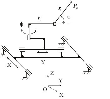
orientation of P 4 on the Hexa-frame. The principle of the carriage mechanism is shown in
Fig. 5. In the application, rotation angle φ is fixed only at a few values, 0°, ±90°, and 180°,
and we can calculate the values of other actuators by fixing φ , i.e., for a given position P4( x,
y, z), the centre of the Hexa-Frame, we have
Hybrid Parallel Robot for the Assembling of ITER
369
X + ( r + r cosϕ) cosφ = x
0
1
,
(3)
Y + ( r + r cosϕ)sinφ = y ,
(4)
0
1
r sin ϕ = Z
1
.
(5)
Then
ϕ = arcsin( Z / r ) ,
(6)
1
X = x − ( r + r cosϕ)cosφ
0
1
,
(7)
Y = y − ( r + r cosϕ) sinφ
0
1
.
(8)
Fig. 5 a) Mechanism of carriage, b) Hexa-WH
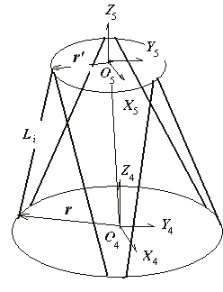
Inverse kinematic model of Hexa-WH: The inverse kinematic model for the Hexa-WH is defined
to find the values for each cylinder at a given position and an orientation of the end-effector
with respect to the Hexa-frame. Here O 4 is coincided with P 4 on the carriage side. Fig.5 b)
demonstrates the coordinates of the Hexa-WH.
The inverse kinematics model for the Hexa-WH is
G
G
=
+ ⋅ ' − ( i = 1, 2, …,6),
(9)
i
L
O O
R
4 5
i
r
i
r
where
⎡ α
c β
c
α
c β
s γ
s − α
s γ
c
α
c β
s γ
c + α
s γ
s ⎤
⎢
⎥
R =
,
⎢ α
s β
c
α
s β
s γ
s + α
c γ
c
α
s β
s γ
c − α
c γ
s ⎥
⎢ − β
s
β
c γ
s
β
c γ
c
⎥
⎣
⎦
370
Parallel Manipulators, Towards New Applications
G ri denotes the vector of the joint of the i th cylinder on the Hexa-frame with respect to frame
o4 and '
ri is the vector of the joint of the i th cylinder on the end-effector with respect to
frame o5.
The length of each cylinder can be found, when ( x, y, z, γ, β, α) is defined with respect to frame o4.
'
G
'
G
l =
= ( O O + R ⋅ − ) • ( O O + R ⋅ − ) .
(10)
i
L
i
4 5
i
r
i
r
4 5
i
r
i
r
There are two ways to combine the two inverse kinematic models to get the solution of the
whole robot. One simple way is to calculate the coordinates (x, y, z, γ , β , α ) of the end-
effector with respect to {O4} and the values for each actuator from equations (3-10) for the
given coordinates of the end-effector with respect to frame {o}, while fixing {O4} at a certain
position with respect to frame {o} according to experience. The another way is to use an
optimization algorithm to find redundant solution, which is subjected to minimize the
deflection of the robot during motion, i.e., min f ( q, l ) , where f is the deflection model of the
l
robot, q is the position vector of the end-effector, and l is the value vector of ten actuators.
For a given q we can find l by solving the optimization problem min f ( q, l ) .
l
4. Control system
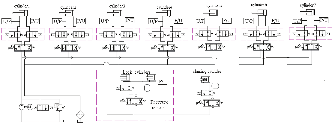
4.1 Hydraulic control system
Fig.6 shows the water hydraulic system. Pressure servo control is applied in locking
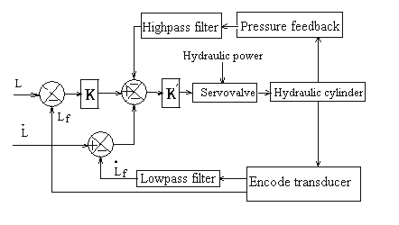
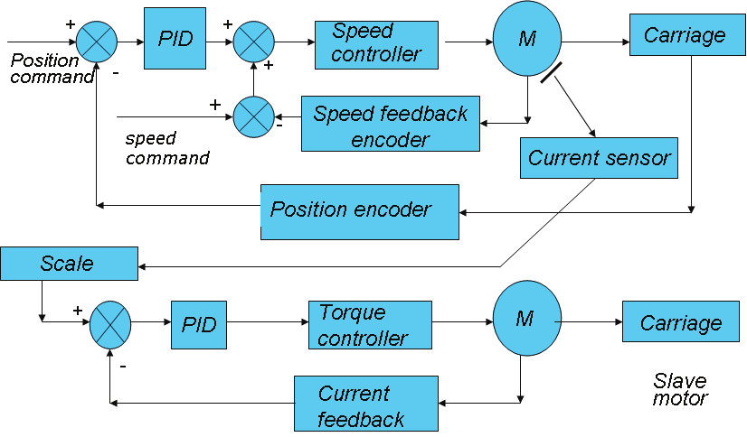
cylinders. Position servo controller is used in cylinders 1-7. There are three loops in the
servo position control: the position loop together with the speed loop that provide an
accurate and fast trajectory tracking; and the load pressure feedback loop that is applied to
damping the self-excited oscillations, which normally occur in the natural frequency. The
speed loop can eliminate the speed error, while the pressure feedback damps the vibration
of hydraulic actuators (Fig. 7).
Fig.6 Water hydraulic circle
Hybrid Parallel Robot for the Assembling of ITER
371
The hydraulic cylinders normally lack damping that makes the cylinder contro