VGTM
6-DOF gripper
Table 1. Function modes and robot configurations
2.2 System decomposition
As a series of modules are required as building blocks for a reconfigurable system, the first
step is to decompose the parallel robot into a series of common modules. For serial robots,
the decomposition into common modules is generally straightforward as serial robots are a
collection of links and joint actuators. These modules are then connected sequentially to
build the final robot architecture. For parallel mechanisms, the decomposition of the robot
system is not as straightforward due to the physical and mathematical constraints of the
system. There does exist though a natural modularity that has generally been overlooked
when dealing with parallel robots as will be shown.
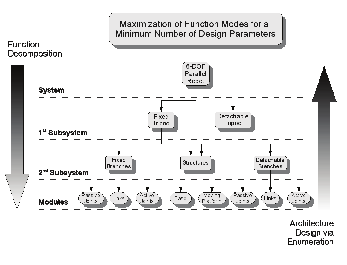
From Fig. 1., a 6-DOF parallel manipulator system is separated into two individual 3-DOF
tripods subsystems. Each tripod subsystem can further be decomposed into a series of
branch subsystems with a common structural subsystem. The 6-DOF robot has only one
base and one moving platform, thus the decomposition of the two tripods results in these
also having a common base and moving platform. Without losing any generality, the branch
subsystems for the two tripods are composed of a collection of link modules, passive joint
modules and active joint modules (i.e. actuators). These modules represent the final level of
decomposition required to describe a generic parallel robotic system. Further decomposition
is also possible and this is where the detailed design and part selection occur and is beyond
the scope of this chapter.
Architecture Design and Optimization of an On-the-Fly Reconfigurable Parallel Robot
383
Fig. 2. System design cycle of a reconfigurable parallel robot
This decomposition is further explained in Fig. 2. It is plain to see that the arrow on the left
side of the figure indicates the direction taken for the system decomposition. The arrow on
the right side of the figure is where the majority of the architecture design occurs. Once the
building blocks (modules) of the reconfigurable system have been identified, then we can
work our way from the bottom-up to establish the optimal system architecture. This is
accomplished by first using the modules to form branch module candidates. A mobility
analysis is performed and enumeration rules are used to eliminate those branch candidates
that cannot fulfill the design requirements. A kinematic and workspace analysis is
performed and then is used to arrive at the final optimal architecture design of the parallel
robot. All of this is performed such that the final design can perform all of the function
modes identified in Table 1.
We note that each level of decomposition brings an additional level of modularity. The
physical modularity was described above. During the architecture design, the modularity
inherent in the assembly of reconfigurable robots will be address. We also note that there is
modularity in the mathematical computations and control for each system level. The
kinematic computations for 6-DOF parallel manipulators, 3-DOF tripod manipulators, open-
chain branches (including simple chains consisting of one joint) are well established. This is
also true of their subsequent control laws and algorithms. Although this is beyond the scope
of this chapter, it is a very important aspect of the advancement of reconfigurable systems.
384
Parallel Manipulators, Towards New Applications
3. Module identification
The module identification stage is the first and second part of the bottom-up architecture
design as seen in Fig. 2. The identification of the components is the first and the
identification of the branch configurations is the second. For reconfigurable systems, the
larger the cache of building block modules, the larger the solution space with a greater
diversity of possible solutions.
3.1 Components
3.1.1 Active joint modules
Active joint modules are the modules that are controllable. Currently, there are numerous
commercially available simple actuation devices (having 1-DOF). They are categorized as
rotational (revolute), or linear (prismatic). The topographical analysis (Tsai et al., 1998) uses
these two categories of actuation devices to enumerate the configurations of some planar
and spatial parallel manipulators. The revolute joint was decomposed into the standard
rotational joint and a twist joint (Dash et al., 2005). Hereafter we will refer to these joints as
transverse revolute joints (RT), and axial revolute joints (RA), respectively. We similarly
decompose the prismatic joint into a fixed-length actuator (PF) where a platform slides along
a fixed guide track, and a variable length actuator (PV) as most commonly seen in Gough-
Stewart platforms. All four of these actuation devices are commercially available and are
included in the identification of feasible branch modules. We also introduce a universal joint
(U*) that has one controllable DOF and one passive DOF as a possible active joint module.
Kinematically, it is represented by the presence of two revolute joints whose axes intersect at
a point and are orthogonal to each other. Physically one axis is attached to an actuation
device.
3.1.2 Passive joint modules
The active revolute joint modules and prismatic joint modules are also identified as passive
modules by removing their ability to be controlled. The other common passive joint
modules are identified as universal (U), spherical (S), and cylindrical (C).
3.1.3 Link modules
The link modules are simply a means of connecting the active and passive joint modules to
each other in series. These can vary in appearance and length depending on the task
requirements, but those parameters are left for the detailed design phase, which is beyond
the scope of this chapter.
3.1.4 Structural components
The structural components of a parallel manipulator consist of the base and moving
platform. The size and shape of these components vary depending on the task requirements
but must be designed so that the based supports the various branches and the platform
supports the end effector. Again, the specifics are left for the detailed design phase and are
beyond the scope of this chapter.
3.2 Branch identification
Using a combinatorial analysis, the branch configurations can be enumerated for their
potential feasibility as either a fixed branch or a detachable branch or both. In general each
Architecture Design and Optimization of an On-the-Fly Reconfigurable Parallel Robot
385
branch in a spatial parallel manipulator must consists of at least two links and three joints.
Branches can consist of any number of joints and links such that the total branch DOF meets
the mobility requirements. For a 6-DOF parallel manipulator with six branches, the branch
DOF must be equal to six (more information on this is covered in the mobility analysis). The
combinatorial analysis is limited to those branches that have two links and three joints for
the following reasons:
•
Smaller branches (those with fewer joints and links) are easier to evaluate
mathematically. With additional joints, there exists the possibility of multiple solutions
for the forward and inverse kinematics of the active and passive joint variables. This
situation is less likely, and sometimes impossible, for two-link, three-joint branches.
•
In both attached and detached configurations, they provide the minimal amount of
joint-link combinations to maintain functionality. This will become more apparent
during the architecture design phase.
•
Branches with a large numbers of links and joints require more physical constraints
when converting from attached to detached configurations, thus making the structure
itself more physically complicated. This is especially true in the case of individual
detached arms. This is a direct result of the configurations presented in Table 1 and will
also become apparent during the architecture design phase.
•
The fewer number of joints within the individual branches leads to a lesser chance of
collision between the branches.
Using the five active joint modules and the seven passive joint modules a total of 78 branch
configurations are identified as being theoretically possible. The only restriction placed on
joint sequence is for the fixed-length prismatic joint in that it must either be placed at the
base or platform position due to the structural advantages of having a rigid connection of
the track. If it were to be place as the middle joint, then it would act as a variable length
prismatic joint and lose all of its structural advantages. Using the notation stated above,
Table 2. summarizes the various configurations.
Active
Configurations
Joint
RT
RTUS, RTSU, URTS, SRTU, USRT, SURT, RTCS, RTSC, CRTS, SRTC, CSRT, SCRT
RA
RAUS, RASU, URAS, SRAU, USRA, SURA, RACS, RASC, CRAS, SRAC, CSRA, SCRA
PF
PFUS, PFSU, USPF, SUPF, PFCS, PFSC, CSPF, SCPF
PV
PVUS, PVSU, UPVS, SPVU, USPV, SUPV, PVCS, PVSC, CPVS, SPVC, CSPV, SCPV
U*UU, UU*U, UUU*, U*RTS, U*SRT, RTU*S, SU*RT, RTSU*, SRTU*, U*RAS, U*SRA,
R
U*
AU*S, SU*RA, RTSU*, SRAU*, PFU*S, PFSU*, SU*PF, U*SPF, U*CU, U*UC, CU*U,
UU*C, CUU*, UCU*, U*PVS, U*SPV, PVU*S, PU*PV, PVSU*, SPVU*, U*CC, CU*C,
CCU*
Table 2. Branch configurations
4. Architecture design
The enumeration part of the design serves the purpose of defining what is deemed
acceptable candidates for the fixed and detachable tripods. A mobility analysis is done to
provide a link between the identified branches and the mobility requirements of both
tripods and is important for the formation of many of the enumeration criteria.
386
Parallel Manipulators, Towards New Applications
4.1 Mobility analysis
From Fig. 1. and Table 1., it can be seen that the reconfiguration of the robot will change the
robot constraints. For example, going from an attached to detached configuration, the robot
must change its constraints in order to constrain the freedom released by the detached
branch(es). Otherwise, the robot would be loose and uncontrollable. Hence, in order to
understand how the robot constraints change during reconfiguration, a mobility analysis is
required. As will be explained later on, solving the constraint equations is a priori to solving
the inverse kinematics.
In general, the reconfigurable parallel robot under study can be categorized to have attached
and detached configurations. The mobility requirements are thus different for different
configurations. In the attached configuration, the parallel robot is a 6-DOF parallel robot.
The mobility of a system is given by the following equation
nj
F = λ ( n − n − + ∑ f
(1)
l
j
)1
i
i 1
=
where F denotes the mobility or the effective DOF of a parallel mechanism, λ is the order of
the system ( λ = 3 for planar motion, and λ = 6 for spatial motion), nl is the total number of
the links, nj is the total number of the joints, and fi is the number of DOF for the ith joint.
For a parallel manipulator, the branch connectivity can be calculated using Euler's equation.
Through some mathematical manipulation it can be shown that the sum of the connectivity,
Ck, of the kth branch is equal to the total DOF of the system
n
n
b
j
∑ C = ∑ f = F −λ n − n −
(2)
k
i
( l j )1
k 1
=
i 1
=
where nb is the number of attached branches. Further manipulation shows that the
connectivity of each branch must be less than or equal to the order of the system, and it
must be greater than or equal to the mobility of the moving platform
λ ≥ C ≥ F
(3)
k
The full derivation has previously been derived and can be found in (Tsai, 1998). Table 3.
shows a summary the mobility analysis for the various robot configurations, including the
connectivity of the kth branch.
Parallel Robot Configuration
Variable Symbol
3-DOF 4-DOF 5-DOF 6-DOF
System Order
λ
6 6 6 6
Degrees-of-Freedom
F
3 4 5 6
Number of Links
nl
8 10 12 14
Number of Joints
nj
9 12 15 18
Branch Connectivity
Ck
5, 5, 5
6, 6, 5, 5
6, 6, 6, 6, 5 6, 6, 6, 6, 6, 6
Number of Constraints
m
3 2 1 0
Table 3. Mobility analysis summary
Architecture Design and Optimization of an On-the-Fly Reconfigurable Parallel Robot
387
4.2 Enumeration criteria
With the branch configurations identified and connectivity constraints established, the
enumeration process can now be performed to eliminate some of the branch configurations.
Since there are two tripods which are functionally different, there are two sets of
enumeration criterion for the elimination of branch configuration. There is some overlap in
branch elimination criteria between the two tripods and these are addressed first followed
by the tripod-specific enumeration rules.
4.2.1 Fixed and detachable tripod enumeration criteria
The active joint must be placed on, or near the base. This requirement is what generally gives
parallel robots their payload-to-weight advantages. If the active joints (i.e. motors) are
placed at or near the base, then the majority of mass/inertia to be driven is in the platform
and end effector. All configurations with the active joint at the platform are eliminated.
A spherical joint must be located at the moving platform. As will be shown later, the presence of a
spherical joint in the branch is most advantageous if it is located at the moving platform. It
provides a natural pivot point for the moving platform. Thus the elimination of all branches
without a spherical joint, and those with spherical joint modules at the base or middle
position is necessary.
In the fully connected configuration, the motion profile for all branches must be spatial. In the fully
detached configuration, the motion profile for both the individual fixed and detached tripod branches
must be planar. Although these may seem obvious, it helps in the elimination of some of the
branch configurations that are not capable of these mobility requirements. For the fully
detached configuration and those branches with kinematic constraints in the partially
detached configurations, the plane of motion of the branch must orthogonal to the base and
parallel to a plane passing through the joint at the base, and the base joint directly opposite
to it. This eliminates all branch configurations with an active or passive axial revolute joint
module.
After these enumeration criteria are applied, a total of 15 configurations remain as
possibilities for the fixed and detachable tripod branches which are summarized in Table 4.
Active
Configurations
Joint
RT
RTUS, URTS, RTCS, CRTS
PF
PFUS, PFCS
PV
PVUS, UPVS, PVCS, CPVS
U*
U*RTS, RTU*S, PFU*S, U*PVS, PVU*S
Table 4. Acceptable fixed and detachable branch configurations after applying initial
enumeration criteria
4.2.2 Fixed branch enumeration criteria
Fixed branches must have one lockable DOF. As seen in Table 3., the connectivity requirements
for the fixed branches change according to the number of the branches that are either
attached or detached from the moving platform. A fully attached parallel robot
configuration requires each branch to have a connectivity of 6-DOF and a fully detached
parallel robot configuration requires each branch to have a connectivity of 5. Thus it is
388
Parallel Manipulators, Towards New Applications
required that there exists a joint that has a lockable DOF. The lockable DOF must exist on a
joint with 2-DOF for the following reasons:
•
If a single DOF joint is locked, it then forms a rigid bond between the two link modules
that it is attached to, thus reducing the number of links in the branch from two to one.
One link does not allow for proper articulation of the moving platform and therefore
single DOF joints cannot be locked.
•
For the 3-DOF spherical joint, it is possible to lock out one of the DOF, but is not
necessarily easy. Since, the spherical joint is positioned at the moving platform, locking
one of these DOFs will cause the branch to have spatial motion, which as previously
mentioned as unacceptable.
From this, there are three possible joint modules that are candidates for a lockable DOF; one
axis of the passive universal joint module; the revolute axis of the passive cylindrical joint
module, or; the passive axis of the 1 DOF controllable universal joint module. Although this
rule does nothing to eliminate branch configurations, it is important to establish this
criterion when it comes to the physical design of the robot itself.
Fixed-length vs. variable length prismatic joints. For structural considerations, having a fixed-
length prismatic joint at the base is more advantageous than having a variable length
prismatic joint. We thus eliminate the PVUS, PVCS, and PVU*S branches.
Branches with identical modules, but different sequences. One of the previous enumeration
criteria was that the active joint module and thus motor should be placed at the base or close
to it (i.e. the second joint position). There are several remaining branch configurations that
have the same joint modules, but vary in sequence. Again, the advantages of keeping the
motor on the base itself as opposed to at the second joint enables the elimination of those
branch configurations that have identical modules and the active joint module in the
middle. Thus the URTS, CRTS, and the RTU*S configurations.
As seen in Table 5., this does not eliminate all of the configurations with an active module in
the middle joint position, rather just the ones that are less advantageous. A total of nine
branch modules remain as candidates for the fixed branch tripod. Also shown is the
configuration required for the branch(es) after reconfiguration into the 3, 4 or 5-DOF
configurations. It is seen that there are six unique configurations after reconfiguration.
Active Joint
Configurations
RT
RTUS → RTRTS RTCS → RTPVS
PF
PFUS → PFRTS PFCS → PFPVS
PV
UPVS → RTPVS CPVS → PVPVS
U*
U*RTS → RTRTS PFU*S → PFRTS U*PVS → RTPVS
Table 5. Potential fixed tripod branch module configurations
4.2.3 Detachable branch enumeration criteria
Detachable branches must transform from a closed loop 6-DOF connected arm, to a 2-DOF, serial
arm. To maintain usability of the detached arms, and maintain the requirement of planar
motion in the fully detached or partially detached configurations, there must be two
controllable axes. Since the arm will detach from the spherical joint module connection,
there is still a total of 3-DOF and two links. One of these DOF is already controllable, so to
satisfy the requirements, one of the other axes must be controllable, and the other lockable.
Architecture Design and Optimization of an On-the-Fly Reconfigurable Parallel Robot
389
For proper articulation, the control must be present at each joint location. This is
summarized in Table 6. where the reconfiguration of the detachable arms are shown. It is
seen that after reconfiguration, several of the branches are kinematically identical, but are
not physically identical. The reconfiguration requires that passive universal joints become
active transverse revolute joints, passive revolute joints become active while the passive axis
on the 1-DOF controllable universal joint locks, and the passive cylindrical joint becomes an
active variable length prismatic joint. Although, this enumeration criterion does not
eliminate any branch modules, it is important as it establishes the kinematic and physical
requirements that each branch must adhere to after reconfiguration.
Initial Active Joint
Configurations
RT
RTUS → RTRT, URTS → RTRT, RTCS → RTPV, CRTS → PVRT
PF
PFUS → PFRT
PV
UPVS → RTPV
U*
U*RTS → RTRT, RTU*S → RTRT, PFU*S → PFRT, U*PVS → RTPV
Table 6. Reconfiguration of the detachable tripod branch module configurations
Detachable branches must have acceptable reach beyond the height of the moving platform. It is
obvious that the detachable branch must be able to reach the moving platform, but here we
require that they extend beyond the position of the platform for greater usability. Although
this requirement is ambiguous and there is no clear definition of what is acceptable, we
eliminate those branches that have prismatic actuation after disconnection. It is clear to see
that a 2-DOF robotic arm with two revolute joints has a larger potential reach than those
with prismatic joints. The notion of potential reach is based on the length of the links and
those links connected to revolute joints are traditionally longer in parallel manipulators than
their prismatic counterparts.
Branches with identical modules, but different sequences. The four branches that reconfigure into
the RTRT configuration are acceptable as candidates for the detachable branches, and all four
cases require the second joint to be independently actuated. In the attached configuration
however, only one joint is driven and therefore in this configuration it is beneficial to drive
the joint at the base. After elimination, the only branch configurations that are candidates for