straightforward. When the three detachable branches form a three-fingered gripper, the
problem falls into that of grasping kinematics (Montana, 1998). Furthermore, the proposed
system provides an additional advantage in that the detachable tripod can be coordinated
with the fixed tripod to perform auxiliary tasks such as performing a tool change on the
moving platform, or using a sensor to scan a part. Again, this adds another level of
flexibility into the system.
6. Workspace analysis
With the kinematics established, the position workspace volume and boundary of the robot
can be calculated. In each case, a grid of the independent variables as defined in Table 7. is
searched. The finer the independent variable grid spacing, the closer the estimated
workspace volume and boundary is to the true workspace volume and boundary. However
this comes at a computational cost especially with the 5 and 6-DOF cases. At a preliminary
architecture design phase, accuracy can be traded for low computational cost and faster
computational time of the robot workspace. As the design evolves to the detailed design
phase, accuracy is much more important and longer computations are required to achieve
an accurate workspace volume and boundary.
6.1 Physical parameters
The shape and size of a robot's workspace is dependent on its physical parameters such as
link lengths, joint limits, etc. These parameters may or may not be known at the architecture
Architecture Design and Optimization of an On-the-Fly Reconfigurable Parallel Robot
399
design phase depending on the requirements of the system. In order to evaluate the various
configurations, the physical parameters for the base and moving platform are uniform
throughout. The radius of the base, bi, is 100 mm and the radius of the moving platform, r, is
50 mm. In the 6-DOF case, the branches are spaced at 60° intervals. The spacing increases as
necessary when the detachable branches are disconnected from the moving platform. The
physical constraints for each branch configuration are described in Table 8.
Branch
Configuration
Variable Symbol
Value
Lower arm length
l1i
125 mm
RTUS and U*RTS
Upper arm length
l2i
125 mm
Fixed Branches1
Joint variable range
θi
0° - 180°
Guide way inclination
ηi
45°
PFUS and PFU*S
Arm length
li
100 mm
Fixed Branches
Joint variable range
si
0 mm – 100 mm
UPVS and U*PVS
Fixed Branches
Joint variable range
si
125mm – 200 mm
Guide way inclination
θi
135°
CPVS Fixed
Joint variable range
si
125 mm – 200 mm
Branches
Cylindrical joint linear range
li
0 mm – 150 mm
Arm length
l2i
150 mm
R
Cylindrical joint inclination angle
γi
90°
TCS Fixed
Branches
Joint variable range
θi
0° - 180°
Cylindrical joint linear range
li
0 mm – 150 mm
Lower arm length
l1i
150 mm
Detachable
Upper arm length
l2i
150 mm
Branches1, 2
Joint variable range
θi
0° - 180°
Table 8. Branch physical constraints
Finally, we ignore the physical constraint that would be imposed due to the presence of the
spherical joints. In reality, contact between the edge of the socket and the extension of the
ball would impede further motion and thus affect the shape of the workspace. The
1 To avoid singularities, the z-coordinate of the ith middle joint must be less than the z-
coordinate of the ith d i vector.
2 The lengths of the detachable branch arms are consistent for all fixed branch
configurations except the RTCS configuration in which both arms lengths are 250 mm. The
change in length was to provide and an acceptable workspace boundary.
400
Parallel Manipulators, Towards New Applications
alignment of the spherical joints is left to the detailed design phase, as careful design and
alignment can alleviate this impedance.
6.2 Workspace
With the kinematic equations established and the physical parameters defined, the position
workspace can finally be calculated. Table 9. shows the summary of workspace.
Fixed Branch
Robot Workspace Volume [mm3]
Configuration
3-DOF 4-DOF 5-DOF 6-DOF
RTUS and U*RTS
7549
13, 778
15, 595
29, 463
PFUS and PFU*S
15, 368
18, 224
14, 309
17, 265
UPVS and U*PVS
13, 263
9386
6275
6813
CPVS
9619 4634 1898 2244
RTPVS
43 161 2928
6021
Table 9. Workspace volume of the reconfigurable parallel robot
(a)
(b)
(c)
(d)
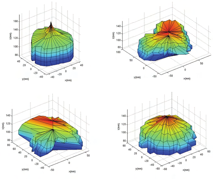
Fig. 10. Workspace boundaries of the PFUS and PFU*S fixed branch configuration: (a) 3-DOF,
(b) 4-DOF, (c) 5-DOF, (d) 6-DOF
Architecture Design and Optimization of an On-the-Fly Reconfigurable Parallel Robot
401
Note than the increase in DOF does not necessarily result in an increase in workspace
volume. This is due to the constraints of the branches and not the kinematic constraints of
the position and orientation of the moving platform. Also, in the 4 and 5 DOF cases, the
spacing of the branches is not uniform and results in very odd shaped workspace
boundaries. An example of the PFUS and PFU*S workspace is shown in Fig. 10.
7. Optimal configuration
The optimal configuration depends heavily on the type of task the robot is required to
perform. Some examples for parallel robotics include:
•
Flight simulation test beds use 6-DOF hydraulically actuated UPVS branches.
•
Machining tool applications use the PFUS branch configuration due to their structural
stiffness.
•
Pick and place automation use planar Delta robots (specialized RTUS branches).
We further note that the optimization here is not the optimization of a continuous system.
Here, there are five discrete systems that require some form of comparison to evaluate their
strengths and weaknesses. There are many methods of evaluating the merits of discrete
systems. These usually include some for of design decision matrix and there are many
works available that covers this topic. All of these methods require a certain degree of
designer input and different designers will form their decision matrices different. Once an
architecture is chosen, then continuous optimization algorithms can be used.
(a)
(b)
(c)
(d)
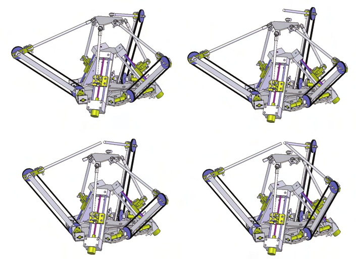
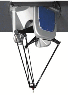
Fig. 11. Reconfigurable parallel robot currently being developed at Ryerson University:
(a) 6-DOF, (b) 5-DOF, (c)4-DOF, (d) 3-DOF
402
Parallel Manipulators, Towards New Applications
A very simple a pair-wise comparison of the discrete systems against each of for the
specified functional requirements is used to arrive at the optimal configuration (Salustri,
2008). Using this design decision method, the optimal architecture of the parallel robot is the
PFUS configuration. This robot configuration is currently being developed at Ryerson
University and is shown in Fig. 11 and the actual prototype is shown in Fig. 12. Also in
development, is a universal joint capable of locking one DOF in order to satisfy the branch
constraint requirements previously described.
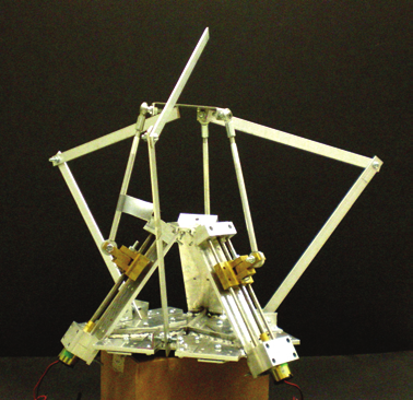
Fig. 12. The prototype of the proposed reconfigurable parallel robot
8. Conclusion
A novel method for the architecture design of a reconfigurable parallel robot is presented
based on common actuation devices. System design techniques are used to classify parallel
robot modules and enumeration rules are established to determine the feasible robot
architectures. Branch kinematics are developed and a workspace analysis is performed. An
optimal design is selected from the remaining discrete robot configurations. The final design
is a self-reconfigurable parallel robot that has the ability to perform on-the-fly
reconfiguration. The proposed reconfigurable parallel robot not only provides innovation in
reconfigurable system design but also stimulates new research into parallel robot
kinematics.
9. References
Chen, I.-M. (2001). Rapid response manufacturing through a rapidly re-configurable robot
workcell. Robotics and Computer-Integrated Manufacturing, 17, 3, (June 2001) pp. 199-
213, 0736-5845.
Chen, L., Xi, F., Macwan, A. (2005). Optimal module selection for designing reconfigurable
machining systems. ASME Journal of Manufacturing Science and Engineering, 127, 1,
(February 2005) pp. 104-115, 1087-1357.
Architecture Design and Optimization of an On-the-Fly Reconfigurable Parallel Robot
403
Dash, A.K., Chen, I.-M., Yeo, S.H., Yang, G. (2005). Task-oriented configuration design for
reconfigurable parallel manipulator systems. International Journal of Computer
Integrated Manufacturing, 18, 7, (October-November 2005) pp. 615-634, 0951-192X.
Hafez, M., Lichter, M.D., Dubowsky, S. (2003). Optimized binary modular reconfigurable
robotic devices . IEEE/ASME Transaction on Mechatronics, 8, 1, (March 2003) pp. 18-
25, 1083-4435.
Hamlin, G.J., Sanderson, A.C. (1997). TETRABOT: a modular approach to parallel robotics.
IEEE Robotics and Automation Magazine, 4, 1, (March 1997) pp. 42-50, 1070-9932.
Horner, C.G., (1990). Adaptive truss structure. US/Japan Workshop on Smart/Intelligent
Materials and Systems, Honolulu, March 1990, 19-23.
Salustri, Filipo A., (2008) http://deseng.ryerson.ca/xiki/Learning/Main:Web_home
Koren, Y., Heisel, U., Jovane, F., Moriwaki, T., Pristchow, G., Ulsoy, G., Van Brussel, H.
(1999). Reconfigurable manufacturing systems. Annals of the CIRP, 48, 2, pp. 527-
540, 0007-8506.
Michael, J. (1995). Fractal shape changing robot construction theory and application note .
Robodyne Cybernetics Ltd.
Montana, D.J. (1998). The kinematics of contact and grasp. International Journal of Robotics
Research, 7, 3, (June 1998) pp. 17-32, 0278-3649.
Onoda, J., Fu, D.-Y., Minesugi, K. (1996). Two-dimensional deployable hexapod truss .
Journal of Spacecraft and Rockets, 33, 3 (May-June 1996) pp. 416-421, 0022-4650.
Sabater, J.M., Saltarén, R.J, Aracil, R. (2005). Design, modelling and implementation of a 6
URS parallel haptic device . Robotics and Autonomous Systems, 47, 1, pp. 1-10, 0921-
8890.
Schenker, P., Pirjanian, P., Huntsberger, T., Aghazarian, H., Baumgartner, E., Iagnemma, K.,
Rzepniewski, A. (2000). Reconfigurable robots for all-terrain exploration .
Proceedings of the SPIE Symposium on Sensor Fusion and Decentralized Control in
Robotic Systems, pp. 454-468, 0277-786X, Boston, September 2000, Society of Photo-
Optical Instrumentation Engineers, Bellingham, WA, USA.
Suh, N.P. (1990). The principles of design . Oxford University Press, New York.
Tomita, K., Murata, S., Yoshida, E., Kurokawa, H., Kokaji, S. (1996). Reconfiguration method
for a distributed mechanical system , In: Distributed Autonomous Robotic Systems 2.
Asama, H., Fukuda, T., Arai, T., Endo, I. (Ed), pp. 17-25, Springer-Verlang New
York Inc., 4431701907, Secaucus, NJ, USA.
Tsai, Lung-Wen. (1998). Systematic enumeration of parallel manipulators . Department of
Mechanical Engineering and Institute for Systems Research, Technical Report, pp. 1-11.
Unsal, C., Kiliccote, H., Patton, M., Khosla, P. (2000). Motion planning for a modular self-
reconfiguring robotic system . Distributed Autonomous Robotic Systems, 4, pp. 1-10.
Xi, F., Verner, M., Ross, A. (2000). A reconfigurable hexapod system—preliminary results .
Proceedings of the 2000 Japan-USA Symposium, Special Session on Modular and
Reconfigurable Controller for Flexible Automation, University of Michigan, July 2000.
Xi, Fengeng, Xu, Yuonan, Xiong, Guolian. (2006). Design and analysis of a re-configurable
parallel robot . Mechanisms and Machine Theory, 41, 2, (February 2006) pp. 191-211,
0094-114X.
404
Parallel Manipulators, Towards New Applications
Yim, M. (1994). Locomotion with a unit-modular re-configurable robot . Ph.D. Thesis,
Stanford University.
Yim, M., Zhang, Y., Duff, D. (2002). Modular robots . IEEE Spectrum, 39, 4 (February 2002)
pp. 30-34, 0018-9235.
19
A Novel 4-DOF Parallel Manipulator H4
Jinbo Wu1 and Zhouping Yin2
1 Traffic Science & Engineering College
2State Key Laboratory of Digital Manufacturing Equipment and Technology
Huazhong University of Science & Technology
China
1. Introduction
Parallel manipulators have the advantages of high stiffness and low inertia compared to
serial mechanisms. Based on the Steward-Gough platform architecture, a lot of 6-DOF
mechanical devices have been proposed. The 6-DOF parallel manipulators suffer from a
small workspace, complex mechanical design, and difficult motion generation and control
due to their complex kinematic analysis. To overcome these shortcomings, the limited-DOF
manipulator, which has fewer than 6 DOFs, can be found in many production lines. It is clear
today that most attention has been paid to 3-DOF family among the limited-DOF parallel
manipulators (Carretero, 2000). However, in many industrial situations, there is a need for
equipment providing more than 3-DOFs. For example, for most pick-and-place applications
in semiconductor manufacturing, at least 4 DOFs are required (3 translation to move the
carried die from one point to the other, 1 rotation to adjust the orientation in its final
location). A new family of 4-dof parallel manipulators called H4 that could be useful for
high-speed pick-and-place applications is proposed by Pierrot and Company (Pierrot, 1999).
The H4 manipulator offers 3 DOFs in translation and 1 DOF in rotation about a given axis.
The H4 manipulator is useful for high-speed handling in robotics and milling in machine-
tool industry since it is a fully-parallel mechanism with no passive chain and able to provide
high performance in terms of speed and acceleration.
This chapter discusses the kinematic analysis of the H4 manipulator. In section 2, synthesis
methods for designing H4 are presented, and various possible mechanical architectures of
the parallel manipulator are exposed. Section 3 discusses the inverse and forward
kinematics problem of H4. Section 4 deals with singularity analysis of H4 utilizing line
geometry tools and screw theory. Section 5 concludes this chapter by providing the
development tendency of the parallel manipulators.
2. Structural synthesis and architectures
2.1 General concept of H4
Parallel manipulators are constituted of a moving platform that is connected to a fixed base
by several chains (limbs). Generally, the number of limbs is equal to the degrees of freedom
(DOF) of the moving platform such that each limb is driven by no more than one actuator
and all actuators can be mounted on or near the fixed base. By acting on the limbs the
406
Parallel Manipulators, Towards New Applications
platform pose (position and orientation) is controlled. Moreover, if the actuators are locked,
the manipulator will become an isostatic structure in which all the legs carry the external
loads applied to the platform. This feature makes the parallel manipulators with high
stiffness possible throughout the whole space. From the first ideas proposed by Gough
(Gough, 1956) or Steward (Steward, 1965), a lot of interesting mechanical devices or design
methods have been extensively studied. In the beginning, many structures were based on
the ingenuity of the researchers and not on a systematic approach. Subsequently, a new
research domain called structure (or type) synthesis was proposed, in which vaious
methodologies were tried to generate all the structures that have a desired kinematic
performance. The most widely used synthesis approaches (and their variants) are graph
theory, group theory and screw theory (Merlet, 2006). In this section, we will not discuss these
theoretical problems, but focus on the structure generation of H4.
The 6-DOF parallel manipulators generally suffer from a small workspace, complex
mechanical design and difficult motion generation and control due to their complex
kinematic anslysis. To overcome these shortcomings, new structures for parallel
manipulators having less than 6-DOF (which are called limited-DOF manipulators in this
chapter, although many of these new structures were known well before) are explored.
There is an overriding motivation behind such efforts: limited-DOF manipulators may be
needed for many applications. For example, parallel wrists need only three rotational DOFs.
It is clear today that most attention has been paid to 3-DOF family among the limited-DOF
parallel manipulators (Gosselin & Angeles, 1989; Agrawal et al., 1995; Gosselin & St-Pierre,
1997; Fattah & Kasaei, 2000; Gregorio, 2001). However, in many industrial situations, there is
a need for equipment providing more than 3 DOFs arranged in parallel and based on
simpler arrangements than 6-DOF strctures. The reference (Cheung et al., 2002) developed a
4-DOF parallel manipulator E4 which could be used in a semiconductor packaging system.
It is in the early 80’s when Reymond Clavel comes up with the brilliant idea of using
parallelograms to build a parallel robot with three translational and one rotational degree of
freedom (Bonev, 2001). Contrary to opinions published elsewhere, his inspiration was truly
original and does not come from any parallel mechanism patents. Professor Clavel called
his creation the Delta robot. The new family of 4-DOF parallel manipulators called H4 that
could be useful for high-speed pick-and-place applications is just based on the idea of Delta
structure (Pierrot & Company, 1999; Company & Pierrot, 1999). The prototype built in the
Robotics Department of LIRMM can reach 10g accelerations and velocities higher than 5m/s
(Robotics Department of LIRMM).
2.1.1 Delta structure
Even if an incredibly large number of different structures have been proposed by academic
researchers in the last 30 years, most of these that are used widely in industry can be
classfied into two basic types: the Delta structure and the so-called “hexapod“ with 6 U-P-S
chains in parallel (U-P-S: Universal-Prismatic-Spherical). This may be a result of either the
exceptional simplicity of the Delta 3-DOF solution, or the enormous research effort
dedicated to “hexapod“ (Company, 1999).
The basic idea behind the Delta parallel robot design is the use of parallelograms. A
parallelogram allows an output link to remain at a fixed orientation with respect to an input
link. The use of three such parallelograms restrain completely the orientation of the mobile
platform which remains only with three purely translational degrees of freedom. The input
A Novel 4-DOF Parallel Manipulator H4
407
links of the three parallelograms are mounted on rotating levers via revolute joints. The
revolute joints of the rotating levers are actuated in two different ways: with rotational (DC
or AC servo) motors or with linear actuators. Finally, a fouth leg is used to transmit rotary
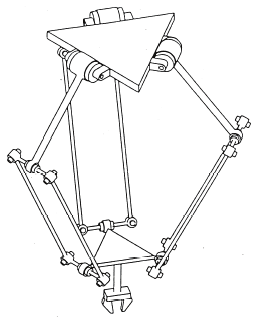
motion from the base to an end-effector mounted on the mobile platform. Fig.1 shows the
most famous Delta robot with three translation degrees of freedom, which was initially
developed at École Polytechnique from Lausanne by Clavel (Clavel, 1988). All the kinematic
chains of this robot are of the RRPaR type: a motor makes a revolute joint rotate about an
axis w. On this joint is a lever, at the end of which another joint of the R type is set, with axis
parallel to w. A parallelogram Pa is fixed to this joint, and allows translation in the direction
parallel to w. At the end of this parallelogram is a joint of the R type, with axis parallel to w,
and which is linked to the end effector.
Fig.1. The Delta structure proposed by Prof. Clavel and one of its industrial version, the
CE33 (courtesy of SIG Pack Systems)
The Delta robot is firstly marked by the two Swiss brothers Marc-Olivier and Pascal
Demaurex who created the Demaurex company (Bonev, 2001). The joint-and-loop graph of
the Delta robot and one of its equivalent structures are shown in Fig.2, where P, R and S
represent prismatic, revolute and spherical joint respectively. The displacement of the end-
effector of the Delta robot is the result of the movement of the three articulated arms
mounted on the base, each of which are connected to a pair of parallel rods. The three
orientat