Straight forward conceptually and simple to implement
Can be implemented with fast convolution
Always stable
Relatively insensitive to quantization
Can have linear phase (same time delay of all frequencies)
Better for approximating analog systems
For a given magnitude response specification, IIR filters often require much less computation than an equivalent FIR, particularly for narrow transition bands
Both FIR and IIR filters are very important in applications.
Choose a desired response, based on application requirements
Choose a filter class
Choose a quality measure
Solve for the filter in class 2 optimizing criterion in 3
Most of the time, people do L∞ optimal design, using the Parks-McClellan algorithm. This is probably the second most important technique in "classical" signal processing (after the Cooley-Tukey (radix-2) FFT).
Most of the time, FIR filters are designed to have linear phase. The most important advantage of FIR filters over IIR filters is that they can have exactly linear phase. There are advanced design techniques for minimum-phase filters, constrained L2 optimal designs, etc. (see chapter 8 of text). However, if only the magnitude of the response is important, IIR filers usually require much fewer operations and are typically used, so the bulk of FIR filter design work has concentrated on linear phase designs.
In general, for –π≤ω≤π H(ω)=|H(ω)|ⅇ–(ⅈθ(ω)) Strictly speaking, we say H(ω) is linear phase if H(ω)=|H(ω)|ⅇ–(ⅈωK)ⅇ–(ⅈθ0) Why is this important? A linear phase response gives the same time delay for ALL frequencies! (Remember the shift theorem.) This is very desirable in many applications, particularly when the appearance of the time-domain waveform is of interest, such as in an oscilloscope. (see Figure 3.1)

For linear phase, we require the right side of Equation to be ⅇ–(ⅈθ0)(real,positive function of ω) . For θ0=0 , we thus require h(0)+h(M−1)=real number h(0)−h(M−1)=pure imaginary number h(1)+h(M−2)=pure real number h(1)−h(M−2)=pure imaginary number ⋮ Thus h(k)=h*(M−1−k) is a necessary condition for the right side of Equation to be real valued, for θ0=0 .
For
 , or
ⅇ–(ⅈθ0)=–ⅈ
, we require
h(0)+h(M−1)=pure imaginary
h(0)−h(M−1)=pure real number
⋮
⇒
h(k)=–(h*(M−1−k))
, or
ⅇ–(ⅈθ0)=–ⅈ
, we require
h(0)+h(M−1)=pure imaginary
h(0)−h(M−1)=pure real number
⋮
⇒
h(k)=–(h*(M−1−k))
Usually, one is interested in filters with real-valued coefficients, or see Figure 3.2 and Figure 3.3.
 (Anti-Symmetric Filters).
h(k)=–(h(M−1−k)).
(Anti-Symmetric Filters).
h(k)=–(h(M−1−k)).
Filter design techniques are usually slightly different for each of these four different filter types. We will study the most common case, symmetric-odd length, in detail, and often leave the others for homework or tests or for when one encounters them in practice. Even-symmetric filters are often used; the anti-symmetric filters are rarely used in practice, except for special classes of filters, like differentiators or Hilbert transformers, in which the desired response is anti-symmetric.
So far, we have satisfied the condition that
 where
A(ω)
is real-valued. However, we have
not assured that
A(ω)
is non-negative. In general,
this makes the design techniques much more difficult, so most
FIR filter design methods actually design filters with
Generalized Linear Phase:
where
A(ω)
is real-valued. However, we have
not assured that
A(ω)
is non-negative. In general,
this makes the design techniques much more difficult, so most
FIR filter design methods actually design filters with
Generalized Linear Phase:
 , where
A(ω)
is real-valued, but possible negative.
A(ω)
is called the amplitude of the frequency
response.
, where
A(ω)
is real-valued, but possible negative.
A(ω)
is called the amplitude of the frequency
response.


 .
.
Time-delay introduces generalized linear phase.
For odd-length FIR filters, a linear-phase design
procedure is equivalent to a zero-phase design procedure
followed by an
 -sample delay of the impulse response. For
even-length filters, the delay is non-integer, and the
linear phase must be incorporated directly in the desired
response!
-sample delay of the impulse response. For
even-length filters, the delay is non-integer, and the
linear phase must be incorporated directly in the desired
response!
The truncate-and-delay design procedure is the simplest and most obvious FIR design procedure.
Is it any Good?
find
h[n] ,
0≤n≤M−1
, maximizing the energy difference between the
desired response and the actual response: i.e., find
 by Parseval's relationship

Since
 this becomes
The best we can do is let
 Thus
h[n]=hd[n]w[n]
,
Thus
h[n]=hd[n]w[n]
,
 is optimal in a least-total-sqaured-error
(
L2, or energy) sense!
is optimal in a least-total-sqaured-error
(
L2, or energy) sense!
Why, then, is this design often considered undersirable?
 (a)
A(ω)
, small M
|  (b)
A(ω)
, large M
|
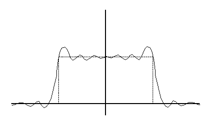
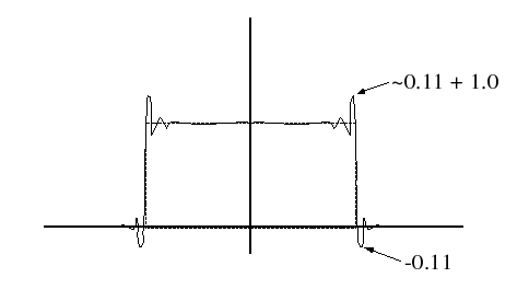
For desired spectra with discontinuities, the least-square designs are poor in a minimax (worst-case, or L∞) error sense.
Apply a more gradual truncation to reduce "ringing" (Gibb's Phenomenon)
The window design procedure (except for the boxcar window) is ad-hoc and not optimal in any usual sense. However, it is very simple, so it is sometimes used for "quick-and-dirty" designs of if the error criterion is itself heurisitic.
Given a desired frequency response, the frequency sampling design method designs a filter with a frequency response exactly equal to the desired response at a particular set of frequencies ωk.
Desired Response must incluce linear phase shift (if linear phase is desired)
What is Hd(ω) for an ideal lowpass filter, cotoff at ωc?
This set of linear equations can be written in matrix form

or
 So
So