Think of when you drop a pebble into a pond, you will see circular waves eminate from the point where you dropped the pebble.

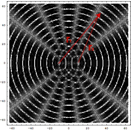
When you drop two pebbles side by side you will see a much more complicated pattern:

Likewise with electromagnetic waves, you can get interesting interference phenomena when waves eminate from two point sources.
Lets take a particular example of two point sources separated by a distance d.
The waves emitted by point source are spherical and thus can be written
 To make the problem easier we will make the
k
's
the same for the two sources. Also lets set the
E0's
to be the same as well.
To make the problem easier we will make the
k
's
the same for the two sources. Also lets set the
E0's
to be the same as well.
The
the only difference in the waves will be the
r
's,
that is

 Now there is a slightly subtle point here that is important to understand. In
the denominator it is sufficient to say that
r1
≈
r2
and just call it
r
.
We assume that we are far enough away that the differences between
r1
and
r2
are too small to matter. However this is not true in the argument of the
harmonic function. There, very small differences between
r1
and
r2
can have a big effect. So lets define
r1
=
r2
=
R
Now there is a slightly subtle point here that is important to understand. In
the denominator it is sufficient to say that
r1
≈
r2
and just call it
r
.
We assume that we are far enough away that the differences between
r1
and
r2
are too small to matter. However this is not true in the argument of the
harmonic function. There, very small differences between
r1
and
r2
can have a big effect. So lets define
r1
=
r2
=
R
 Now to evaluate the final term we use
cos
(
θ
−
φ
)
=
cosθ
cosφ
+
sinθ
sinφ
and write
So we
have
Now to evaluate the final term we use
cos
(
θ
−
φ
)
=
cosθ
cosφ
+
sinθ
sinφ
and write
So we
have
Clearly I will be a maximum when the cosine is = +1
k
Δ
r
=
2
n
π
n
=
0
,
1
,
2
…
 Δ
r
=
nλ
There will be a minimum when the cosine is = -1
k
Δ
r
=
nπ
n
=
1
,
3
,
5
…
Δ
r
=
nλ
There will be a minimum when the cosine is = -1
k
Δ
r
=
nπ
n
=
1
,
3
,
5
…
 So you get light and dark bands which are called interference fringes.To
reiterate; we have two rays of light eminating from two point sources. We
have looked at the combined wave at some point, a distance
r1
from the first source and a distance
from the second source. In that
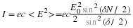
case we find that the intensity is proportional to
So you get light and dark bands which are called interference fringes.To
reiterate; we have two rays of light eminating from two point sources. We
have looked at the combined wave at some point, a distance
r1
from the first source and a distance
from the second source. In that
case we find that the intensity is proportional to
 To make things easier we can redefine
E0
to be the amplitude of the waves at the point under consideration, that is
I
=
ε0c
E02
(
1
+
cosk
Δ
r
)
.
Or we can say
I0
=
ε
c
E02
/
2
and write
I
=
2
I0
(
1
+
cosk
Δ
r
)
.
To make things easier we can redefine
E0
to be the amplitude of the waves at the point under consideration, that is
I
=
ε0c
E02
(
1
+
cosk
Δ
r
)
.
Or we can say
I0
=
ε
c
E02
/
2
and write
I
=
2
I0
(
1
+
cosk
Δ
r
)
.

Say we place a screen a distance S away from the two sources:
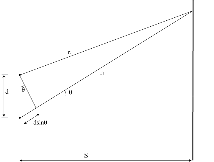
In
this case we see that
Δ
r
=
d
sinθ
So
we have maxima at
Δ
r
=
nλ
=
d
sinθ
.
The
angle between two maxima is given by
 or
for small
θ
or
for small
θ
 Notice
how when the sources are moved far apart the effect maxima become very close
together so the screen appears to be uniformly illuminated. If a screen is
placed a distance S away the maxima on the screen will occur such that
d
sinθ
=
nλ
but
in the small angle limit
Notice
how when the sources are moved far apart the effect maxima become very close
together so the screen appears to be uniformly illuminated. If a screen is
placed a distance S away the maxima on the screen will occur such that
d
sinθ
=
nλ
but
in the small angle limit
 which
implies
which
implies
 likewise
minima will occur at
likewise
minima will occur at
 using
using
 we can rewrite
I
=
2
I0
(
1
+
cosk
Δ
r
)
as
we can rewrite
I
=
2
I0
(
1
+
cosk
Δ
r
)
as

Young's double slit.is an excellent example of two source interference. The equations for this are what we worked out for two sources above. Interference is an excellent way to measure fine position changes. Small changes in Δ r make big observable changes in the interference fringes.
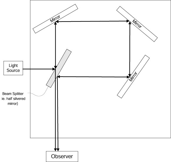
A particularly useful example of using interference is the Michelson interferometer. This can be used to measure the speed of light in a medium, measure the fine position of something, and was used to show that the speed of light is a constant in all directions.
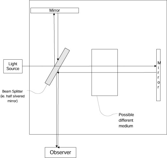
When
Δ
r
,
the path length difference in the two arms is
Δ
r
=
nλ
then the rays of light in the traveling down the center of the apparatus will
interfere constructively. As you move off axis the light travels slightly
different lengths and so you get rings of interference patterns. If you have
set up the apparatus so that
Δ
r
=
nλ
and then move one of the mirrors a quarter wavelength then
 and you get destructive interference of the central rays. Thus you can easily
position things to a fraction of a micron with such a set up.
and you get destructive interference of the central rays. Thus you can easily
position things to a fraction of a micron with such a set up.
What really matters is the change in the optical pathlength. For example you could introduce a medium in one of the paths that has a different index of refraction, or different velocity of light. This will change the optical pathlength and change the interference at the observer. Thus you can measure the velocity of the light in the introduced medium.
Michelson and Morely used this technique to try to determine if the speed of light is different in different directions. They put the whole apparatus on a rotating table and then looked for changes in the interference fringes as it rotated. They saw no changes. In fact they went so far as to wait to see what happened as the earth rotated and orbited and saw no changes. They thus concluded that the speed of light was the same in all directions (which nobody at the time believed, even though that is the conclusion you draw from Maxwell's equations.)
Another application of interference is a a gyroscope, ie. as device to measure rotations.
If the apparatus is rotating, then the pathlengths are different in different directions and so you can use the changes in the interference patterns to measure rotations. This is in fact how gyroscopes are implemented in modern aircraft.
Suppose there is a very thin film of dielectric and light is incident on it normally. Lets consider single reflections. (We make the small angle of incidence approximation)
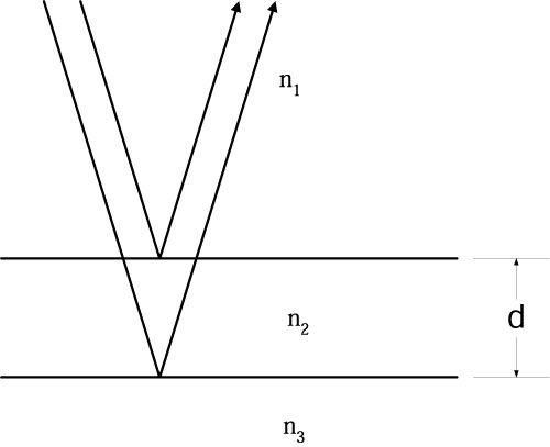
We
will assume
n3
>
n2
>
n1.
The physical path length difference of the reflected light is
Δ
r
=
2
d
.
We will get maxima in the interference when:
Δ
r
=
2
d
=
m
λ2
m
=
1
,
2
,
3
…
where
λ2
is the wavelength in the film. Now
λiνi
=
c
/
ni
.
In our example we have
ν1
=
ν2
=
ν3,
that is the frequency does not change moving between the media. So we have
λ1n1
=
λ2n2
=
λ3n3
.
Thus constructive interference will happen when
 where
nfilm
=
n2.
Destructive interference will happen when
(
2
d
)
nfilm
=
m
λair
/
2
m
=
1
,
3
,
5
…
where
nfilm
=
n2.
Destructive interference will happen when
(
2
d
)
nfilm
=
m
λair
/
2
m
=
1
,
3
,
5
…
When destructive interference occurs then that value of λ is not reflected. Note that this is a function of both d and λ . The next effect is that different colours of light get reflected at different thicknesses of the film. This is why soap films or oil films on water give rainbow effects.
Note I have assumed that n3 > nfilm > nair in the above, where n3 is the material that the film sits upon.
Consider an interface between two materials with indices of refraction n1and n2. If n2 > n1. Then lets examine what happens to the phase of an electromagnetic wave upon reflection. For a transverse electric field, there is a phase change of π . For the transverse magnetic field (or E∥ ) there is not, if the light ray is close to the normal. However if n1 > n2 then and the situation is reversed and the transverse electric field does not undergo a phase change and the transverse magnetic field does. In the example above, their will be no relative phase change between the rays in either case. Either both will change by π or neither will change, depending on the orientation of the E field.
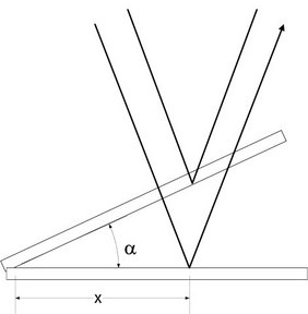
Assume that the normally incident light bounces off the bottom of the top glass and the top of the bottom glass. In this case there is a phase change between the two cases and the conditions of constructive and destructive interference flip.
So constructive interference occurs when 2 d = n