with the swivel hook attached to the rope socket on
the drilling line.
9-9
FM 5-484/NAVFAC P-1065/AFMAN 32-1072
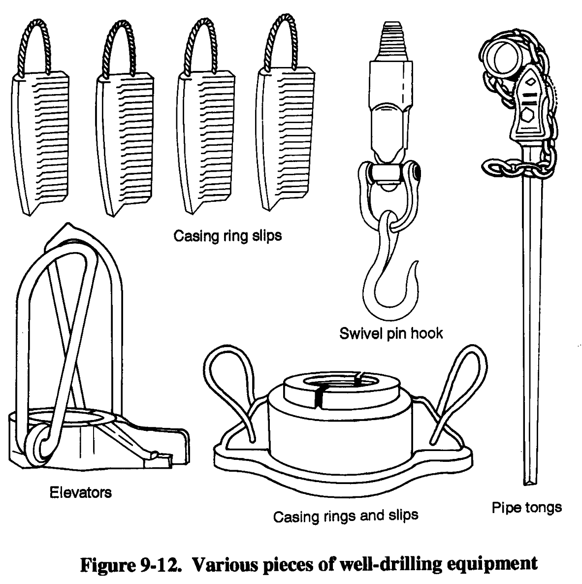
(7) Casing Ring and
Slips (Figure 9-12). Use
a casing ring to suspend
the casing at the ground
surface and for pulling
pipe from the hole using
jacks placed under each
side of the casing ring.
The rings are made of cast
steel and are fitted with
handles. All slips are cast
steel, with sharp teeth
properly hardened.
(8) Pipe Tongs
(Figure 9-12). Use chain
tongs to tighten the 6- and
8-inch drive pipe.
Should the pipe turn in
the hole while adding a
top length, hold the lower
pipe with one tong and
tighten the top length
with another. If friction
in the borehole is enough
to hold the pipe while
making up top lengths, use both tongs on the top length, opposite each other. Doing so puts an even strain on the pipe, eases the operation, and makes abetter joint. Pipe joints must be tight and kept tight while driving pipe; however, keep tong pressure low enough to avoid collapse of the pipe.
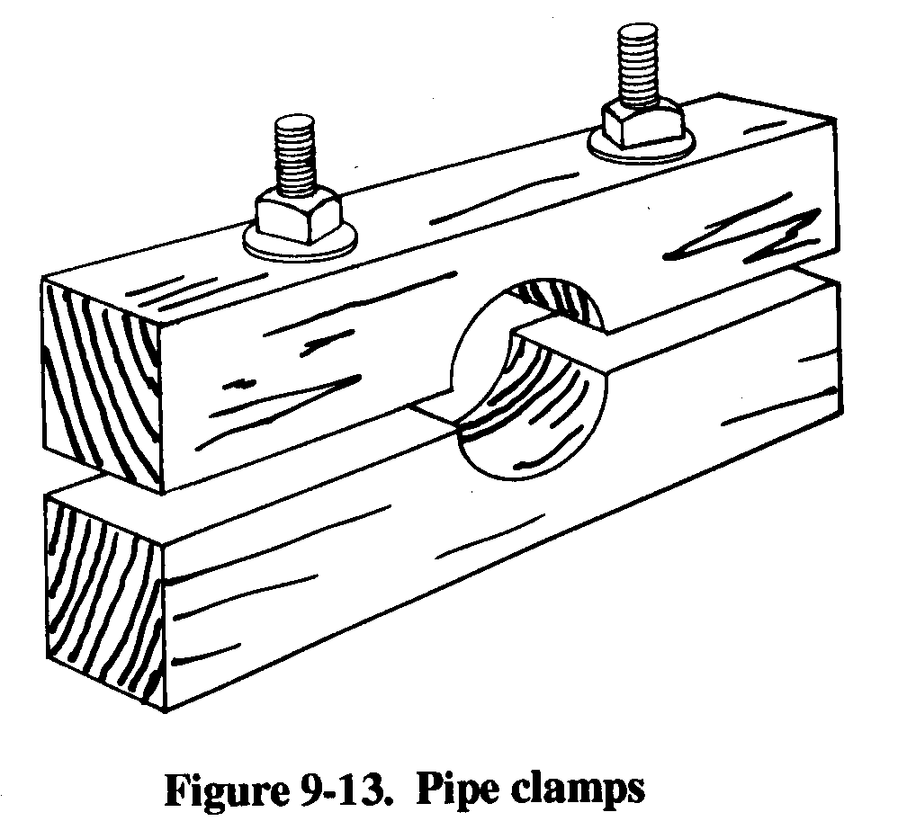
(9) Pipe Clamps (Figure 9-13). You can
construct wooden pipe clamps for 6- and 8-inch
drive pipe. You can use the clamps to hold the pipe
at any position in the hole during drilling
operations.
b. Procedures.
(1) Borehole. Generally, driven wells are
started in a hole bored with a hand auger. The
diameter of the borehole should be larger than that
of the well point, and the borehole should be as
deep as the auger will work. In clay soils, boring
with an auger is much faster than drilling.
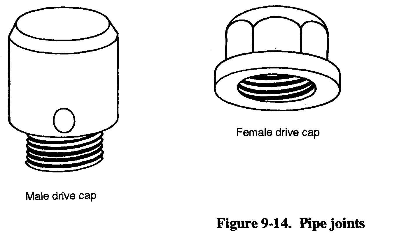
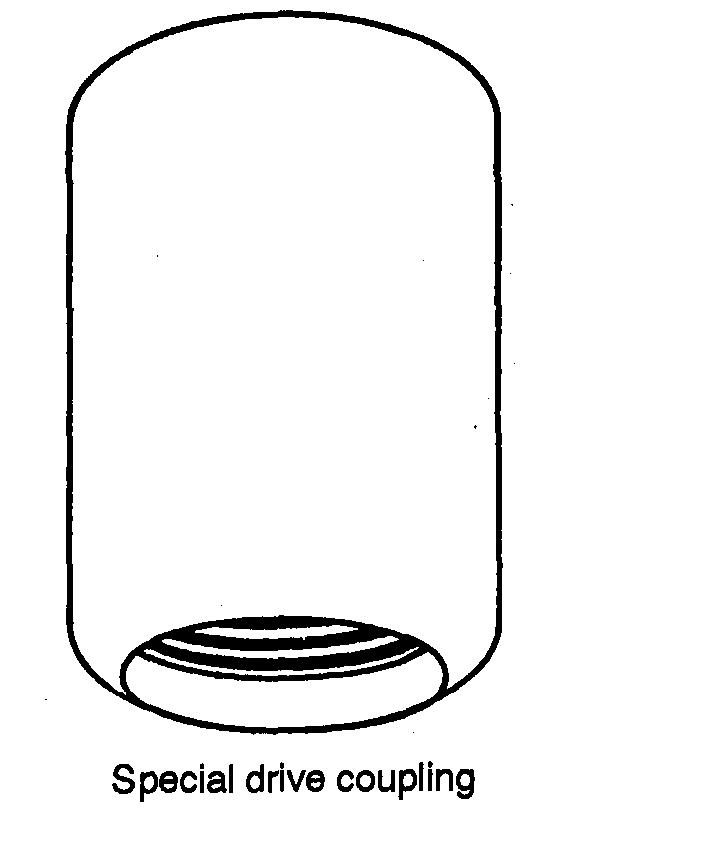
(2) Pipe Joints.
Construct pipe joints
carefully so that joints are airtight to prevent
threads from breaking. If available, use special
9-10
FM 5-484/NAVFAC P-1065/AFMAN 32-1072
drive-pipe couplings (Figure 9-14). Screw all joints tightly after cleaning and oiling the threads. Use joint compound to improve airtightness. When transporting and storing joints, you should protect them with caps or couplings. To ensure that joints remain tight, give the pipe a fraction of a turn with a wrench after each blow until the upper pipe joint sets permanently. Do not twist the pipe string while driving.
(3) Pipe. You must keep the well pipe vertical. To check the angle, hold a plumb bob at arm’s length from the well pipe and from two directions at right angles to each other. If the pipe is not vertical during the early part of the driving, straighten it by pushing on the pipe while the blows are delivered. If you cannot straighten the pipe, withdrew it and start in a new location.
Use a maul or sledge to strike the drive capon the well pipe. Hit the drive cap squarely to avoid pipe damage. An alternative to manual driving is a driver that fits over the drive cap. If available, use a pneumatic tamper or sheet pile driver with an air compressor if the pipe is strong. A weak pipe will break at the couplings if you do not use a butt joint.
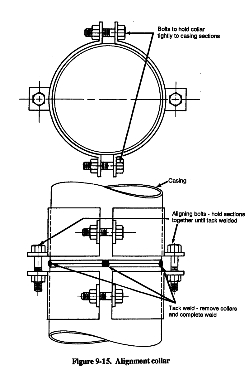
(4) Casing. If you use unthreaded casing, butt-weld the casing lengths. Use an alignment
to get a straight, tight joint. With the welded casing, you can drive a pipe string and possibly eliminate casing damage. Remove the collars when you complete tack welding.
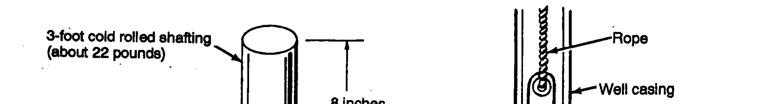
Another driving method involves a steel driving bar attached to a rope. The bar falls freely
because it does not weaken the pipe.
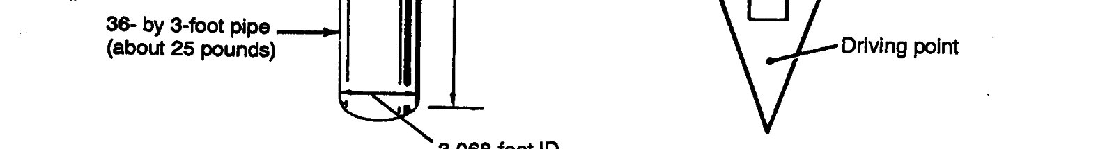
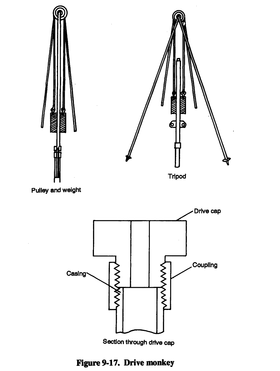
The falling-weight method uses a drive monkey, which is a weight that slides over the pipe
(Figure 9-17, page 9-14). A simple arrangement of this method is one in which the monkey slides
on a bar supported by the well pipe. Use a drive cap with this arrangement. Another method is to slide the drive monkey over the well pipe to strike the drive clamp that is around the well pipe. You must use a tripod with either method. In soft formations, the descent rate may be 2 or 3 inches per blow. In sand or compact clay, using water in and around the pipe makes driving easier. Extremely compact clay is difficult to penetrate and requires many blows to penetrate a few inches.
9-11
FM 5-484/NAVFAC P-1065/AFMAN 32-1072
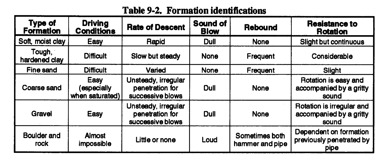
Successful construction of driven wells depends on close observation and correct interpretation of certain work aspects while driving. Interpretation of details such as penetration made with each blow, drop and rebound of the maul or weight, sound of the blow, and resistance of the pipe to
rotation helps the well driver to determine the character of the materials being penetrated. Table
9-2 (page 9-15) outlines a guide for the identification of the formation being penetrated.
9-12


FM 5-484/NAVFAC P-1065/AFMAN 32-1072
c. Well Completion.
(1) Straight-Pumping Method. You can develop a well with a pitcher-spout hand pump. The pump has a plunger and a check valve arranged so that the check valve trips when you raise the pump handle as high as possible. With this method, you can pump for an extended period before tripping the check valve. Tripping allows water to run back down the well pipe. By applying a heavy suction on the well and tripping the valve, you produce a surging action through the screen openings. The flow reversal, due to the surging, loosens the fine material plugging the screen openings and brings the fine sand and silt into the well point. If you pump continuously for severe 1minutes, these particles may be raised from the well. When the flow is clear, the well is ready for use. Check the pump to ensure that the valves and plunger are free of sand.
(2) Alternative Completion Methods. If you cannot clear all the sediment from the well point by pumping, try any of the following methods:
Method 1. Lower a series of connected lengths of 3/4-inch pipe into the well with the lower end resting on the sediment in the well point. Clamp the pipe in position and attach a hand pump to the upper end. Run water into the well pipe (not the 3/4-inch pipe) and operate the hand pumps. By steadily pumping, the sediment will be lifted through the 3/4-inch pipe. Continue to lower the 3/4-inch pipe to the sediment level until the well is cleared.
9-13


FM 5-484/NAVAC P-1065/AFMAN 32-1072
Method 2. Insert a string of 3/4-inch pipe into the well and fill the well with water.
Repeatedly raise and lower the pipe sharply. Hold your thumb over the top of the 3/4-inch pipe during upward movements, and remove your thumb during downward movements.
A jet of muddy water is expelled on each downward stroke. When the material loosens and is suspended, you can pump out the muddy water.
Method 3. Pump water into a string of 3/4-inch pipe that is resting on the sediment to remove the fine material by a jetting action. This procedure requires a large supply of water and a motor-driven or hand-force pump.
9-14
FM 5-484/NAVFAC P-1065/AFMAN 32-1072
9-4. Cable-Tool Method.
a. General. Cable-tool drilling (churn drilling) produces a chopping action. The method and the tool are not expensive, and one person can operate the rig. Cable-tool drilling is a very slow method and is not as widely used as rotary drilling and percussion drilling are used. You can use a cable-tool drill to penetrate rocky soil or moderately hard sedimentary rock. The drill does not require large amounts of drilling fluid. Since the borehole is not full of fluid, you must drive casing as you dig the hole deeper to stabilize the wall.
b. Equipment and Procedure.
(1) Rig. The rig consists of a winch with a large wire-rope reel, a walking beam, and a mast.
Make sure the wire rope is long enough to reach the anticipated depth. Advance the borehole using a suspended bit for chopping the soil or rock at the bottom of the hole. Thread the wire rope through the walking beam and over a sleeve at the top of the mast. As the walking beam goes down, the bit is lifted; as the walking beam comes up, the bit is dropped. As you dig the borehole, unreel the rope to keep the bit just at the bottom. If the borehole is dry, add water to a few feet off the bottom. As you lift and drop the drill bit, the material is chopped and mixed with the water. After an advance of a few feet, use a bailer to remove the mud.
(2) Tools. A complete set of drilling tools includes the chopping bit and a set of heavy drill jars located above the bit. The stroke of the drill jars is such that when the walking beam is all the way down, the bit is above the bottom of the hole. When the walking beam goes up, the bit drops to the bottom of the hole; as the drill jars close, the bit is impacted. Using a drive barrel and long jars, take a sample from the bottom. The stroke of the long jars is longer than the stroke of the walking beam so that the drive barrel is not lifted off the bottom of the hole while driving with the impact of the jars. Cable-tool drilling involves many cycles. Each cycle involves reeling and unreeling wire rope and is a slower operation compared to a cycle on a rotary rig.
9-5. Augered Wells. You can construct bored wells using hand- or power-driven earth augers.
Boring is practical where groundwater can be obtained at shallow depths and when small quantities are needed. Augered boreholes range from 2 to 32 inches in diameter and reach depths of 25 to 50
feet. Engineer troops can construct small-diameter bored wells using organizational equipment.
9-15
FM 5-484/NAVFAC P-1065/AFMAN 32-1072
a. Equipment.
(1) Hand Auger. These augers consist of a shaft or pipe with a wooden handle at the top and a bit with curved blades at the bottom. The standard engineer auger has fixed blades, but there are bits with blades adaptable to different diameters. Hand augers usually come with several shaft extensions and couplings. To add an extension, remove the handle, couple a section to the pipe, and replace the handle. Hand augers can penetrate clay, silt, and those sands in which an open borehole will stand without caving.
(2) Power Auger. These augers are rotated, raised, and lowered by power-driven mechanisms.
The turning force is transmitted to the auger through jointed square or polygonal stems. The power auger issued to engineer troops has a depth limit of about 10 feet. You can use this auger only in areas where the water table is close to the surface.
b. Procedures. To start boring with an auger, force the auger blades into the soil while turning the tool. The auger will cut into the ground at a rate determined by the hardness of the soil. When the space between the blades is full of material, remove the auger and empty it. Repeat the operation until you reach the desired depth.
When constructing bored wells, you may hit small rocks or boulders that will prevent further penetration. When this occurs, lift the auger from the hole; remove the cutting bit, and replace it with a spiral or ram’s horn. Lower the tool into the hole and turn the auger clockwise. The spinal should twist around the rock so you can lift the rock to the surface. Remove the spiral, replace it with the regular bit, and continue boring. If you hit a large boulder that you cannot remove with a spiral, abandon the hole and start somewhere else. Wells less than 15 feet deep should not require equipment other than the auger. For deeper wells, use a light tripod with a pulley at the top or a raised platform so you can insert and remove a longer auger rod from the hole without damaging the rod and without unscrewing all pipe sections.
c. Well Completion. If you reach loose sand and gravel, you may not be able to bore below the water table. To overcome this problem, lower a pipe or other casing to the bottom of the hole and continue to remove material while adding weight at the top of the casing to force the pipe down.
If you cannot remove material from the hole, use a bailer or sand pump and make the hole deeper.
Complete bored wells by installing well screens in the aquifer and developing the well as described
in Chapter 7. You may also use drive points (paragraph 9-3a(l), page 9-6).
If you find groundwater in jointed clay, complete bored wells by lining the hole with clay tile.
Use bell- and spigot-type tile and set the tile in the hole with the bell ends down. Pour coarse sand around the tile. You cannot ensure a sanitary well using this completion method. Therefore, use this method when it is the only possible solution.
9-16


FM 5-484/NAVFAC P-1065/AFMAN 32-1072
Chapter 10
Arctic Well Construction
10-1. Considerations.
a. Arctic Water Supply. Supplying water for operations or bases in the Arctic and adjacent cold regions requires careful planning due to the harsh climate and ground conditions. Potable water is widespread at the surface in some cold regions but is uncommon in more arid cold regions.
Locally, surface water can be melted from ice or pumped from unfrozen lakes or glacial-melt pools.
Many surface sources are only dependable during the summer months, leaving potential problems in supplying water throughout the year. More dependable, year-round supplies of groundwater may be developed through wells in relatively shallow, unfrozen strata (Figure 10-1) and from wells that fully penetrate the permafrost.
WARNING
Do not touch cold metal
with your bare hands.
10-1
FM 5-484/NAVFAC P-1065/AFMAN 32-1072
Permanently frozen rock and soil are widespread in the Arctic north of 50oN latitude. This condition restricts groundwater development because some of the groundwater is permanently frozen and not available. The frozen zones, which vary in thickness from a few feet to 2,000 feet, are impermeable aquicludes and inhibit the upward movement of unfrozen groundwater. The difficulty of obtaining water increases northward as the permafrost thickens and becomes colder and more continuous.
b. Discontinuous Permafrost. In this zone, permafrost will be thin and may be absent on the south slopes of hills, in valley bottoms containing permeable alluvial material (sand and grovel), and under surfaces that have been cleared of vegetation (airport runways, farmlands, forest-fire scars, and logging tracts). Obtain information from local sources regarding springs (icings), existing wells, unfrozen zones, and caves used for storage. Consider obtaining water from surface sources before drilling and developing wells in the permafrost zone. The existence of a good, year-round water source at the surface in the discontinuous zone will indicate that the ground is not frozen beneath the well. Year-round springs, large streams, and lakes can serve as water sources. Even if the water is unpotable, these sources indicate windows in the permafrost where dug, driven, jetted, or drilled wells may be located.
Vegetation could indicate the presence and thickness of permafrost. Tree roots rarely exceed a depth of 3 feet. Therefore, the presence of large trees may indicate that only the top of the permafrost during the thawing season is deeper than usual. Large trees along a river could suggest that either the top of the permafrost is depressed to afford a limited supply of water or that permafrost may be absent. The presence of pine or aspen may indicate a similar depression of the permafrost table or possibly the complete absence of permafrost. The presence of willow shrubs (not trees), peat and moss, or stunted tamarack and birches may indicate a thin zone of summer thawing (active zone) and the presence of cold, thick permafrost near the surface. These indicators are more frequent in a thick, continuous permafrost zone.
c. Thick, Continuous Permafrost. Generally, you will have to use surface sources when underlain by thick, continuous permafrost. Available groundwater will require drilling deep (several hundred feet) wells through the permafrost. Such a task may be beyond the scope of a military operation.
10-2. Well Drilling.
a. Drilling Equipment. You will use the same drilling equipment as for normal well drilling and additional accessories required because of adverse weather conditions. You will need portable gasoline or diesel heaters for personnel and equipment at the construction site. You will also need electrical or oil immersion heaters for storage and settling reservoirs. You should have tents or sheds as protection for personnel from cold winds or storms.
b. Rotary Drilling. In permafrost regions, use the rotary-drilling method for deep drilling and large diameter holes and for shallow drilling and small holes. The procedure for rotary drilling in frigid climates is the same as in temperate climates except for temperature requirements of the drilling fluid. In adverse weather conditions (extremely low temperatures and snowstorms), construct shelters to protect the rigs and to maintain comfortable working temperatures.
At temperatures below -20°F, generally no drilling is done. The mud used in rotary drilling should beat near-freezing temperatures when entering the drill stem to prevent thawing and caving 10-2
FM 5-484/NAVFAC P-1065/AFMAN 32-1072
of the hole. When necessary, apply enough heat to the mud to prevent the hole from freezing. Make sure the rig operates continuously to prevent the mud pump and accessories, bits, and casing from freezing during operations. If you must stop operations at night, remove the tools, let ice form, and drill out the ice in the morning. In a finished well, you can use the rotary rig to circulate the water to prevent freezing until you can install a pump.
c. Jet-Drive Drilling. This is another method of constructing small wells in cold climates. You can also use this method in warm or discontinuous permafrost. The wells are usually 2 inches in diameter and are drilled to a depth of 200 feet. Use the procedures and equipment described in
Chapter 9 to construct the wells.
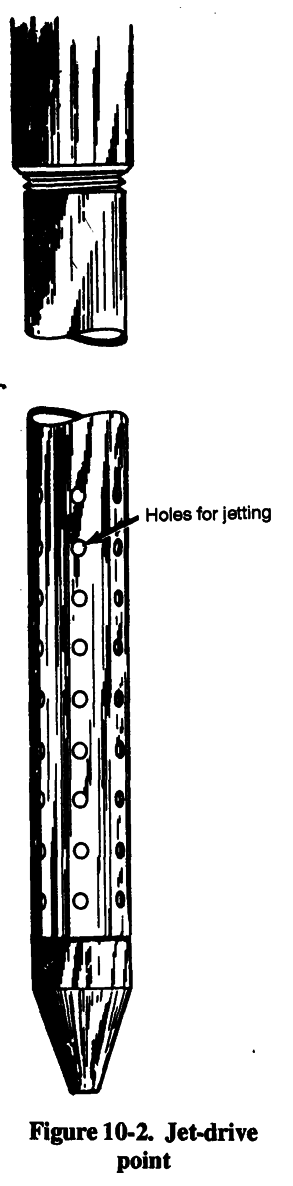
The equipment is simple and light and consists of small derrick and a small engine with a cathead. You push the pipe into the ground and advance it manually dropping a small weight fastened to a line running over a sheave on the derrick to the cathead. The jet point is made from a reducer, which is ground into a bullet shape and attached to the end of the 2-inch pipe. Drill several l/4-inch holes above the jet point a distance of 1 to 2 feet. A thaw-line pipe projects a maximum of 2 feet through the head of the drive point.
Pump a water jet through the thaw-line pipe during drilling operations. Suspend the pipe on a simple chain hoist and slowly move the pipe up and down. The thaw-line pipe will penetrate the sediments ahead of the jet point. When the thaw-line pipe is about 2 feet ahead of the jet point, retract the pipe. The casing is driven as far as it will go; repeat the process. Use water no warmer than 40oF in this process. Jet-drive drilling proceeds about three times as fast in permafrost as in
thawed ground. See Figure 9-2 (page 9-2) for a rig you can use in Arctic well drilling. Figure 10-2
(page 10-4) shows a jet-drive point you should use with the rig.
For depths of 100 feet or less, one man operating a rig can jet drive about 28 feet per day in frozen ground. If the ground is thawing, the footage per day is reduced. The well can yield 40
gallons of water per minute from a 2-inch well equipped with a suction pump with less than 20 feet drawdown. At a depth of more than 100 feet, jet-drive drilling becomes rather slow and difficult.
Therefore, try to limit jet-drive drilling to the southern portions of the permafrost zone.
d. Drilling Fluids. The fluid used in drilling through permafrost must remain in a liquid state during drilling operations and must not contaminate possible water sources. You can eliminate possible contamination through pumping. When using mud, try to keep the mud from freezing by adding chemical agents such as aquagel, gel-flake, barite, fibratex, smentex, micatex, and impermex.
Be careful during periods of excessive permafrost thawing. The hole could slough during drilling.
Do not heat the drilling fluid. An increase in the viscosity of the drilling mud will result in a decrease in mud flow, eventually causing freezing or sticking of the bit.
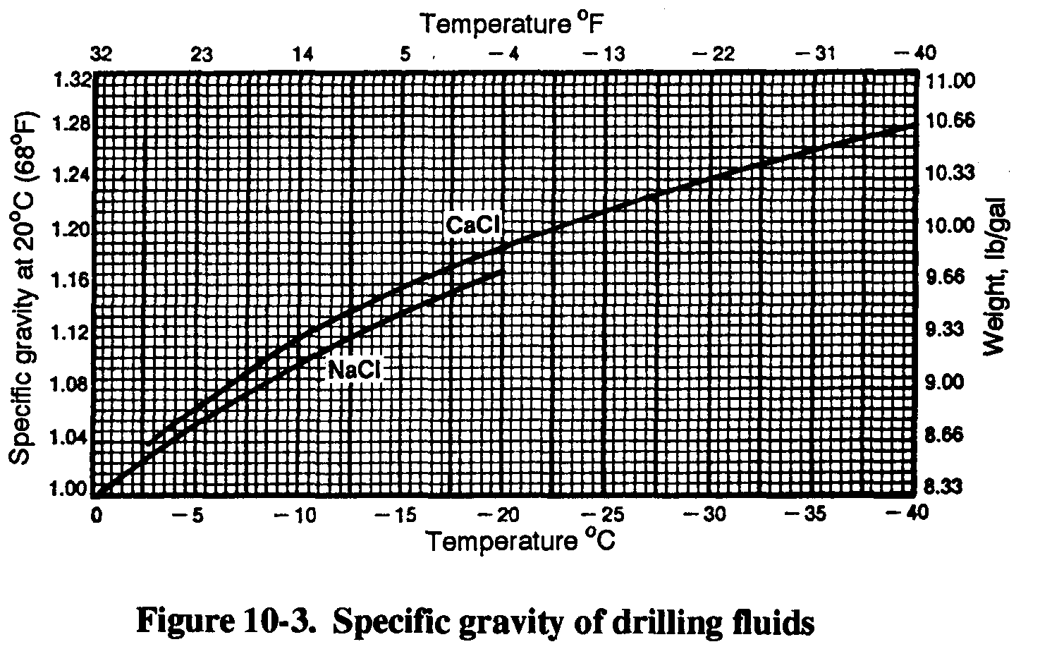
Brine, as a drilling fluid, is not ideal in permafrost areas because it promotes contamination and excessive thawing. It could corrode the drill string, rig, and pump and cause a skin rash on personnel. Use brine sparingly, when required. In normal water-well drilling, you develop the well by pumping after drilling, which clears the well of brine. A suitable brine solution would be 35
pounds of rock salt mixed with 53 gallons of water. In the Arctic, 100 pounds of rock salt is ample
for drilling a 15- to 20-foot hole. (Figure 10-3, page 10-4) shows the specific gravity of drilling
fluids when using salt additives in mud-drilling operations.) You must clean drilling equipment after using brine.
10-3
FM 5-484/NAVFAC P-1065/AFMAN 32-1072
CAUTION
Adding salts to drilling fluids
will reduce the viscosity,
e. Air Rotary Drilling. This is the preferred drilling method for intermediate- or large-depth wells if you have the equipment. You do not have to take the same precautions as with rotary drilling.
f. Well Installation and Completion. You can use some of the same installation and development methods in cold climates as you did in warm climates, with some precautions. Try to minimize prolonged contact of surface water with any permafrost. Doing so will avoid freezing in the hole or thawing and sloughing the previously frozen wall and the need to redrill. You can use the single-string method to install screen and casing together for wells in rock-like permafrost because disturbance is minimal.
The potential for water freezing after the well starts routine production should be reviewed. You could insulate the well by centering a regular well casing in an oversized drill hole and by packing the annulus with dry sand through the permafrost interval.
You could then fit the well for continuous rather than intermittent pumping.
10-4


FM 5-484/NAVFAC P-1065/AFMAN 32-1072
Chapter 11
Auxiliary Activities
11-1. Exploratory Drilling.
a. Geological Exploration.
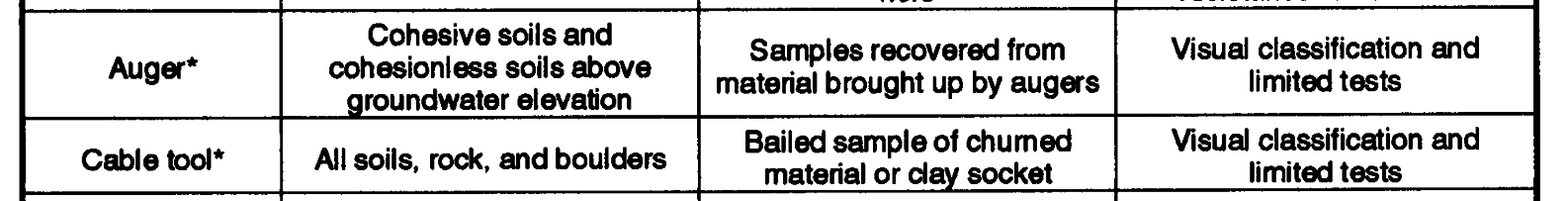
Use the same drilling methods for subsurface geological
exploration as for standard well drilling. However, you will need special accessory equipment. See Table 11-1 for drilling methods and material samples. Auxiliary equipment for exploration drilling may include solid and hollow-stem augers, sampling tubes, core barrels and bits, crackerjack bits, wash casing, and bailers. All the equipment is effective for sampling but varies for exploratory drilling, depending on conditions. In shallow depths, use augers. However, auger samples are disturbed and are not suitable for strength determinations. The samples can provide data such as soil type