

FM 5-484/NAVFAC P-1065/AFMAN 32-1072
and ease of drilling. Igneous aquifers are usually the largest and have the least amount of porosity and hydraulic conductivity and may be tough to drill through. Sandstone and limestone aquifers have properties between sand and grovel and igneous aquifers. If a limestone aquifer is cavernous and is expected to yield large quantities of water, the analyst preparing the overlay could rate the aquifer as a 2. This rating indicates that the aquifer material is better than the 3 rating normally assigned to limestone.
A-6. Potential Drilling Areas. The following are reasons for areas to be eliminated or marked as unsuitable well-drilling sites:
If an aquifer is more than 1,500 feet deep, because military well-drilling machines cannot reach that depth.
If no significant groundwater exists.
If successful well completion is unlikely because of overburden materials, limited aquifer extent, or groundwater barriers restricting water flow.
Besides map legends, Supplemental lnformation should include detailed statements on seasonal groundwater fluctuations, bacterial contamination, geology, and other pertinent information.
Feature, with numbered symbols on the overlay, are entered into a Potential Water-Data Table.
The numbered features include information on the following:
Well location.
Well yield.
Water quality.
Well depth.
Overburden and aquifer materials.
Well use.
Water-chemistry data.
Water fluctuations.
Feature names.
Numbered features on the overlay may also be keyed into a WRDB Analyst Report Form-Record Characteristics form that allows for the recording of particular technical information on the feature.
Information such as construction and design of existing wells, pumping test results, and other data that will aid in the design of new wells or assist in the maintenance of existing wells should be included. Most overlays are classified SECRET or CONFIDENTIAL. To order overlays, write to US Army Topographic Engineer Center, ATTN: CETEC-TC-H, Fort Belvoir, Virginia 22060-5546, or call DSN 345-2921 or commercial (703) 355-2921.
A-4


FM 5-484/NAVFAC P-1065/AFMAN 32-1072
Appendix B
Navy Well Drilling
B-1. General. The Naval Construction Force (NCF) Seabees, as part of their primary mission, are tasked to provide water-well-drilling support for the Marine Corps. Doctrine for this support is in OH13-4/NWP 22-9. Each naval mobile construction battalion (NMCB) table of allowances (TOA) includes four water-well-drilling technicians (NEC 5707) and well-drilling equipment and materials to develop water wells from deep subsurface aquifers. To accomplish the well-drilling missions, well-drilling teams deploy from an NMCB by land, air, or sea.
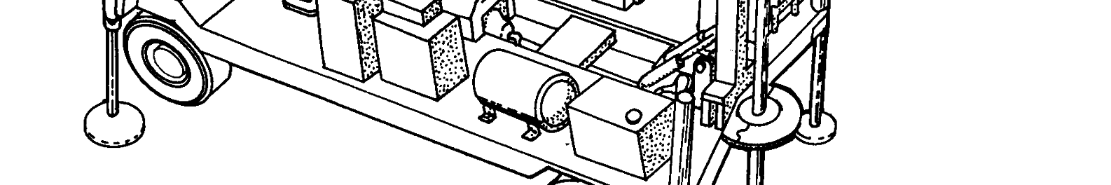
B-2. Equipment. The NMCB TOA includes one International Standards Organization (ISO) air-transportable water drill (ITWD) (Figure B-1), one 750-psi/300-cfm air compressor, and two 1,500-foot well-completion kits.
B-1

FM 5-484/NAVFAC P-1065/AFMAN 32-1072
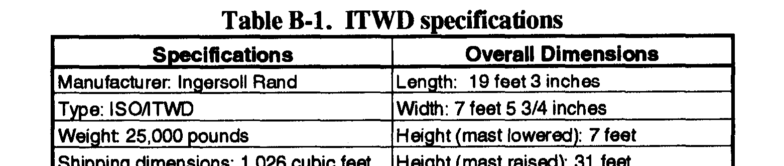
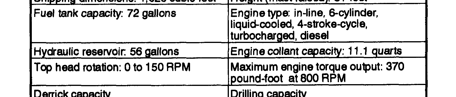
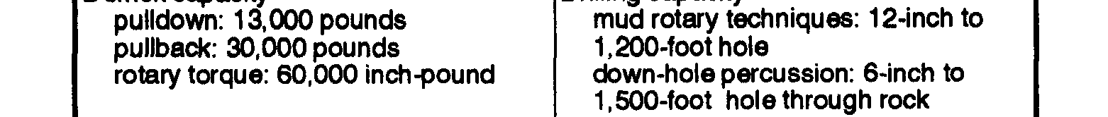
a. The ITWD. This machine replaces the LP- 12 1,500-foot well-drilling machine and the semitrailer-mounted Portadrills, models 501 and 521. The ITWD is an all-wheel-drive, self-propelled rig that can be shipped in a standard 8- by 8- by 20-foot IS0 shipping container. The ITWD can also be shipped on a C-130 or larger aircraft without disassembly. The machine is an all-hydraulic, top-head drive unit with a telescoping mast capable of employing standard 20-foot drill steel. The ITWD has a top speed of 10 miles per hour (mph) and is not designed for over-the-road mobility. It is lightweight, highly mobile, and suitable for rapid deployment with Fleet Marine Force (FMF) engineer units. The machine is compatible with the Service Logistical Vehicle Systems (LVS). See Table B-1 for specifications on the ITWD.
The ITWD is capable of mud and air rotary drilling, rotary percussion, or down-hole hammer drilling, using an auxiliary air compressor. A mud pump, water-injection pump, in-line oiler, four comer-mounted leveling jacks, fore and aft pintle hooks, utility hoist, driller’s station, and driver’s station are mounted on the ITWD. The ITWD is deployed with a kit that includes lightweight drill steel, drill collars, tricone bits, down-hole air hammer, and miscellaneous subs and adaptors for drilling to a depth of 1,500 feet. Because of the various drilling capabilities, the ITWD can drill in any geological formation. If drilling requires the air compressor, it is brought to the site with the drill rig or delivered by a support vehicle. For mud-drilling operations, teams need a water truck and the equipment to dig the mud pits.
b. Air Compressor. One wheel-mounted, diesel-engine-driven, 750-cfm, 300-psig air compressor is included in each NMCB TOA for performing down-hole hammer drilling techniques.
The ITWD is capable of towing this air compressor. The ITWD does not have on on-board air compressor.
c. Well-Completion Kit. Each NMCB TOA includes two 1,500-foot well-completion kits.
Materials in these kits are considered consumable project materials. The kits are used to develop and complete a well. The supported unit is responsible for replacing the materials in the kits.
B-2

FM 5-484/NAVFAC P-1065/AFMAN 32-1072
Appendix C
Air Force Well Drilling
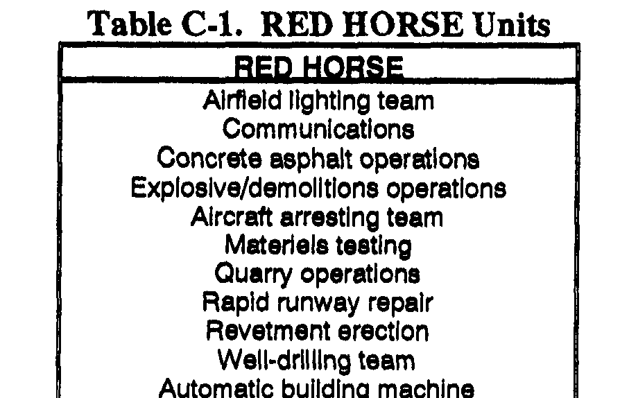
C-1. General. Air Force well-drilling teams are organized and assigned according to Air Force Instruction (AFI) 10-209. This publication outlines the organizational concepts and capabilities of the Rapid Engineer Deployable, Heavy Operational Repair Squadron (RED HORSE). This squadron provides the Air Force with a highly mobile, self-sufficient, rapidly deployable, civil-engineering, heavy construction and repair capability. The Air Force headquarters control RED HORSE. Welldrilling units are assigned as a special-skills team to an operational RED
HORSE unit. The unit provides the logistical support necessary to complete the well-drilling mission and the administrative support well-drilling teams require (Table C-l).
These units are classified for deployment using the following categories: a. RH-1. This is an air-transportable RED HORSE echelon composed of 16 people. An RH-1
team is ready for deployment 12 hours after notification. The squadron can perform advanced airfield surveys and site layout and can prepare for the orderly establishment and future development of a base of operations during contingencies.
b. RH-2. This is an air-transportable RED HORSE echelon composed of 93 people. An RH-2
team is ready for deployment 48 hours after notification. The squadron can erect base shelters and perform limited earthwork and light base development during the initial phase of contingencies.
Light base development includes installing aircraft arresting systems, expedient airfield matting, and essential utility systems.
c. RH-3. This is a RED HORSE echelon composed of 295 people. An RH-3 team is ready for deployment six days after notification. Continental United States (CONUS)-based RH-3
personnel usually deploy by air to the TO where they can be joined with pre-positioned RH-3
equipment. CONUS-based RH-3 equipment usually moves overland to the TO. However, most RH-3 equipment is air-transportable on a C-5. With equipment, an RH-3 team is capable of performing heavy repair, runway repair, facility hardening, and airfield expansion, to include erecting relocatable facilities to support contingency operations.
C-2. Organization and Scope. Well-drilling teams are required to develop and provide adequate water resources for deployed forces.
a. Capabilities. The well drilling teams should be able to do the following: C-l


FM 5-484/NAVFAC P-1065/AFMAN 32-1072
Disassemble, transport, and reassemble the drilling rig.
Set up the well drilling rig and support equipment.
Drill a 1,500-foot, 6-inch diameter well.
Drill with mud, air, and foam circulation.
Drill with down-the-hole hammer.
Drill in sand, soil, clay, rock, or other geological formations.
Perform operator’s service checks and maintenance.
Develop the well for connecting and interfacing with storage facilities and water-distribution systems.
b. Requirements. The hazards and risks associated with water-well drilling require the highest standards of training, proficiency, and safety.
The following publications have specific
responsibilities that apply to water-well operations:
AFI 10-209.
AFI 91-301.
AFI 91-202.
TA 429.
Operations, maintenance, and repair manual for the assigned well-drilling rig.
Repair parts manual.
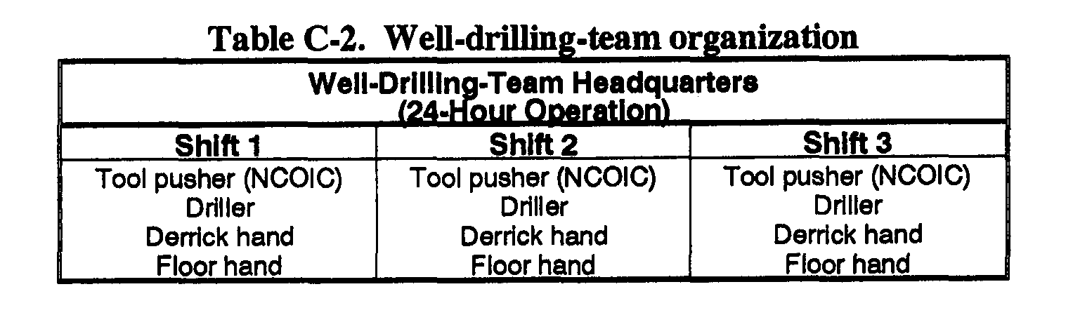
c. Team Composition. A water-well-drilling team will be composed of a minimum of 12
trained personnel. The team must provide a four-man, 8-hour shift, 24-hour drilling operation.
Teams should be primarily 3E2X1 (construction equipment) personnel in grades E3 through E8.
However, other Air Force Specialty Codes (AFSCs) should be considered, such as 3E4X1 (utilities system specialist). The team must consist of 8 RH-2 and 4 RH-3 personnel. The officer in charge or noncommissioned officer in charge of the RH-2 or RH-3 team has the responsibility for well drilling. The 12-man team should be broken down to 3 four-man teams.
Special positions and duties are as follows:
Tool pusher (supervisor). Outlines the drilling program and sees that it is carried out.
Driller. Operates the drilling rig.
Derrick hand. Works in the mast, racks the steel, and so forth.
Floor hand. Makes and breaks the connections, cares for all tools and equipment. Both floor and derrick hands carry out the mud program.
C-2

FM 5-484/NAVFAC P-1065/AFMAN 32-1072
d. Publications and Documentation. In addition to the publications listed in C-2b, each
squadron will maintain, at a minimum, the following standard documentation and publication files: TM 5-545.
Ground Water And Wells (third edition).
Ground Water Hydrology.
Water Well Handbook
Drilling Mud Data Book.
Engineers Handbook.
Percussion of Drilling Equipment Operation and Maintenance Manual. Catalog #500-2.
e. Equipment. The equipment in the RED HORSE units is not standardized and varies in make and model.
C-3

FM 5-484/NAVFAC P-1065/AFMAN 32-1072
Appendix D
Electrical Logging System
D-1. Logging Unit. The DR-74 Electrical Logging System has been designed for use in logging shallow, vertical wells. It is a hand-operated unit. You manually lower and raise the well probe in and out of the well. The operator takes readings point b y point up the well bore and records these readings. The data is plotted on a logging form to get the graphical log needed for interpretation.
When using the gear, you can get a spontaneous potential (SP) curve and three normal and two lateral resistivity curves.
a. Well Probe. The well probe consists of one brass current electrode and three lead-oxide potential electrodes. Each electrode is internally insulated with epoxy resin, and each is connected to the surface by a separate conductor. The potential electrodes are spaced at 0.25, 2.5, and 10 feet from the current electrode. The current electrode is drilled so that an insulated sinker rod can be attached to the probe with a leather thong if more weight is needed to carry the probe to the bottom of the well. With the resistivity instrument at the surface, the operator can read the SP in millivolts and the resistivity in ohm-feet. The reel holds about 500 feet of cable. (An additional 500 feet of cable can be attached to work at depths of 1,000 feet.) A test set is provided for checking the operation of the instrument.
b. Resistivity Instrument. This instrument uses direct current and is of the null reading type.
The instrument reads directly in ohm-feet. The use and operation of the various controls on the instrument panel follow:
Galvanometer. This is a zero-centered micrometer. All operations of the instrument involve returning the meter needle to the zero position.
SP shutoff switch. This is a spring-return switch located in the upper left comer of the panel. The switch automatically shuts off the l-1/2-volt C- battery (used in the SP circuit) when the instrument lid is closed.
Probe selector switch. This switch is located directly below the SP shutoff switch on the units modified for mud logging. When using the switch, the operator can select either the normal probe with the 0.25-, 2.5-, and 10-foot electrode spacings or the mud probe for monitoring conditions in the mud pit or borehole.
Self-potential potentiometer. This instrument balances out the SP that exists between any pair of potential electrodes. You must obtain a balance before making any resistivity reading. Balance is indicated when the galvanometers needle goes to zero. If you want an SP curve, record the potentiometer reading. Each division is one millivolt; a full scale is 1,000 millivolts.
SP polarity-reversing switch. This switch is located directly below the SP potentiometer and shows the polarity of the particular cable electrode being used. When using the switch, the operator can change the polarity of the injected voltage as required by borehole conditions.
Current switch. This is the ON-OFF switch located directly below the function switch; it is a momentary spring-return toggle switch. The spring-return is an automatic shutoff safety feature.
D-1

FM 5-484/NAVFAC P-1065/AFMAN 32-1072
Function switch. This is the three-position selector switch located directly beneath the galvanometers.
The three positions are CUR (current), CAL (calibrate), and LOG
(logging). Use the CUR position when checking the system to determine if you are using the correct amount of current. Use the CAL position when calibrating the instrument.
Calibration is required at the start of the logging operation and after every 50 feet of logging). Use the LOG position during the logging operation.
Calibration adjustment. The CAL ADJUST is located in the lower right-hand comer of the panel and is used to zero the galvanometers when calibrating the instrument.
Ohmmeter. This instrument is located directly above the CAL ADJUST and indicates earth resistivity directly in ohm-feet. A reading at 0.25-foot NORMAL equals 1 ohm-foot for each division and 1,000 ohm-feet at full scale. A reading at 2.5-foot NORMAL equals 10 ohm-feet for each division and 10,000 ohm-feet at full scale. A reading at 10-foot NORMAL equals 40 ohm-feet for each division and 40,000 ohm-feet at full scale.
Electrode selector switch. This five-position switch is located directly above the ohmmeter. On the right side, it makes circuit connections for either the 0.25- or 2.5-foot NORMAL arrangement. When the switch points straight up, the connections are for the 10-foot NORMAL arrangement. On the left side, the connections are for the 0.25- and 2.5-foot LATERAL arrangement, as marked. In the LATERAL arrangements, the 10-foot electrode is the reference for both positions.
Cable jack. This is the four-pronged receptacle located in the upper right comer of the panel. The jumper cable from the logger cable case plugs into the jack thereby connecting the instrument to the well probe.
Potentiometer (POT). This is a black plug receptacle used to connect the surface-potential ground wire (lead-oxide flag) to the instrument.
CUR. This is a red plug receptacle used to connect the surface-current ground wire (steel stake) to the instrument.
Test set. With the test set, you can check the instrument operation and condition of the batteries without using the logging cable. The test set is normally kept in the base of the instrument. To use the set do the following: plug the set into the cable jack, the red plug into CUR, and the black plug into POT. Follow the usual logging procedure. You will have little or no SP. The electrode selector switch may be in any of the NORMAL logging positions.
c. Power Supply. Three power sources of 1 1/2, 9, and 45 volts are requited. You can use a C -size battery for the 1 l/2-volt source and a 9-volt battery for the 9- and 45-volt sources.
d. Logging Cable. This cable used to lower the probe into the well. The cable has four conductors that are made of copper-coated steel wire and are covered with a tough, durable 60
percent natural-rubberjacket. The cable is very resistant to abrasion, is flexible at low temperatures, and has a high breaking strength of 320 pounds. The cable is marked every five feet with numbered markers.
e. Cable Reel and Reel Case. The reel case is made of drawn aluminum. The reel is made of aluminum and PVC. The reel ends ride in bronze bearings attached to the reel case. Whenever possible, nonferrous metals have been used to construct the logging gear. Before removing or D-2


FM 5-484/NAVFAC P-1065/AFMAN 32-1072
installing the reel, unreel the cable to lighten the reel. To remove the reel from the case, unscrew the six screws from each bearing block and carefully lift the reel and bearings from the case.
f. Extender Cable-Reel Assembly. Use this cable when logging past 500 feet. The assembly has an S stamped on the flange to which you mount the jumper connector. This cable must be used first. When you reach the 500-foot marker, attach the second waterproof connector to the cable reel. This connector will be located at the hub of the cable reel assembly. The second cable is then connected to the instrument by means of the jumper.
g. Surface Lines. Two small lengths of stranded-conductor, insulated wire are included with the unit. The red wire has a plug on one end for connecting to CUR on the instrument panel and a clamp at the other end for fastening to a steel stake. (The steel stake is not furnished.) The black wire has a plug on one end for connecting to POT on the instrument panel and a piece of oxidized lead on the other end. If these lines become worn or broken, replace them with any 18- to 20-gauge stranded-conductor, insulated wire. These lines and reels are too large for the instrument cases, so they are carried separately.
D-2. Types of Logging.
a. With the Normal Arrangement.
(1) Setting up Equipment. The equipment required to log a well includes the following: Logging instrument.
Logging cable.
Surface-potential wire (black) with lead-oxide flag.
Surface-current wire (red).
Steel rod that is about 1/4 to 1/2 inch in diameter and 2 to 3 feet in length.
Use the following procedures when preparing to log a well:
Step 1. Plant the lead-oxide flag and the steel rod on opposite sides of the well about 75
feet from the well. Bury the lead-oxide flag, which has been moistened with water and tamped, in a hole about 1-foot deep. Plug the black wire into POT and the red wire into CUR on the instrument panel.
Step 2. Connect the probe assembly to the logging cable only if the waterproof connectors and their pins and sockets are clean. If the connectors do not mate easily after the pins are aligned, apply silicone (spray or grease) to the surfaces. The connectors are mated properly when you hear a pop.
Step 3. Secure the locking rings.
Step 4. Lower the probe to the bottom of the well and plug the jumper cable into the cable receptacle on the instrument panel. On units equipped with a mud probe, place probe selector switch NORMAL.
(2) Calibrating. To calibrate, place the function switch at CAL and the electrode selector switch at any NORMAL position, hold the CUR switch at ON, and zero the galvanometers needle by adjusting the CAL ADJUST knob. Calibrate at the start of each job and after every 50 feet of D-3
FM 5-484/NAVFAC P-1065/AFMAN 32-1072
logging. If cannot zero the galvanometer, you may not have enough current flowing. See paragraph
(3) Logging.
(a) Balancing out SP. With the electrode selector switch at 0.25 NORMAL, turn the function switch to LOG and zero the galvanometers needle b y adjusting the self-potential potentiometer. The dial reading on the potentiometer is the SP in millivolts with the polarity of the probe electrode as indicated on the reversing switch. If you cannot zero the galvanometers, reverse the polarity switch
and try again. If reversing does not work, see paragraph D-3 and paragraph D-4 (page D-6).
(b) Measuring resistivity. After balancing the SP, hold the current switch at ON and return the galvanometers needle to zero by adjusting the ohmmeter. Release the current switch. The dial reading of the ohmmeter is the resistivity for the 0.25-foot NORMAL electrode spacing. Turn the electrode selector switch to 2.5-foot NORMAL and repeat(a) and(b). Multiply the dial reading on the ohmmeter by 10 to obtain the apparent earth resistivity for this electrode spacing.
To obtain a log, the well probe must be below the fluid level in the well. When you pull the probe out of the water, the resistivity instrument will go dead. To quickly check the fluid-level depth, turn the function switch to CUR and hold the current switch at ON, When you pull the well probe out of the fluid, the galvanometers needle will return to zero.
The 0.25- and 2.5-foot NORMAL readings are preferred logs for most wells. If you want an SP curve, the electrode selector switch should be in the 0.25-foot position. However, in a large borehole or in an exceedingly high-formation resistivity, you may have to use the 10-foot NORMAL
position. In the NORMAL position, the instrument is not directly reading. Use 40 as the multiplying factor.
To become proficient in the above procedures, use the test set and practice taking readings.
The spacing between readings depends on the amount of detail being sought. For most situations, take readings every 2.5 feet. In 1- to 2-foot thick formations, take readings every 1 foot to 2 feet up the well born. In logging mud-filled or deep holes, attach a sinker rod to the probe so you can feel the bottom of the well. When using metal, cover the metal with friction or electrical tape and attach the sinker to the well probe with a leather thong.
b. With the Lateral Arrangement. In areas that have highly resistive surface materials (deserts or dunes) or large and varying ground potentials (highly industrialized areas using large direct-current generators), you may not be able to make a normal log. Use a lateral log to overcome these difficulties.
The setup is similar to the NORMAL arrangement except you will not need the lead-oxide surface electrode (POT). You can complete the current circuit (CUR) by attaching the red wire to the well casing or any other good ground. The electrode-selector switch must be in one of the two LATERAL positions. To complete the reading, use the procedure as for the NORMAL
arrangement. However, the meter does not provide a direct reading. For the 0.25-foot lateral, the factor is 1.025 (essentially direct); for the 2.5-foot lateral, the factor is 13.33.
D-4


FM 5-484/NAVFAC P-1065/AFMAN 32-1072
D-3. Mud Probe (on Units Modified for Mud Logging).
a. Calibrating. Unit calibration is a rear panel adjustment and is adjusted for the mud logger probe furnished with the unit. However, the CAL ADJUST potentiometer will effect some adjustment to accommodate changes due to temperature and battery condition. If the rear panel adjustments are not tampered with and the galvanometers needle remains within + 2 minor divisions of zero when calibrating the instrument in the CAL position of the function switch, the calibration of the instrument will be + 10 percent of the obtained reading.
Unit checkout of the instrument in the mud mode of operation with the test set may be done as in the normal mode with the results obtained. Electrode switch must be in one of the following NORMAL positions:
CUR position -at 10 divisions.
CAL position - within + 2 divisions of zero.
LOG position - reading on ohmmeter of about one-tenth the value marked on test set or as indicated on resis