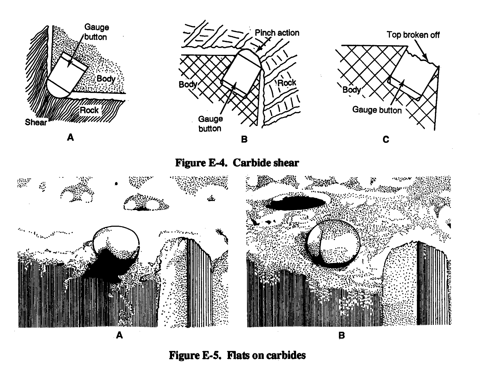
Buttons must be ground to restore their original shape at
the first sign of a developing flat. High rotation speeds tend to accelerate the development of flats on the carbide. Although RPM will vary with local conditions, rotating the bit faster will not increase
the penetration rate but will increase the chances of shearing a carbide (Figure E-5, B).
E-2
FM 5-484/NAVFAC P-1065/AFMAN 32-1072
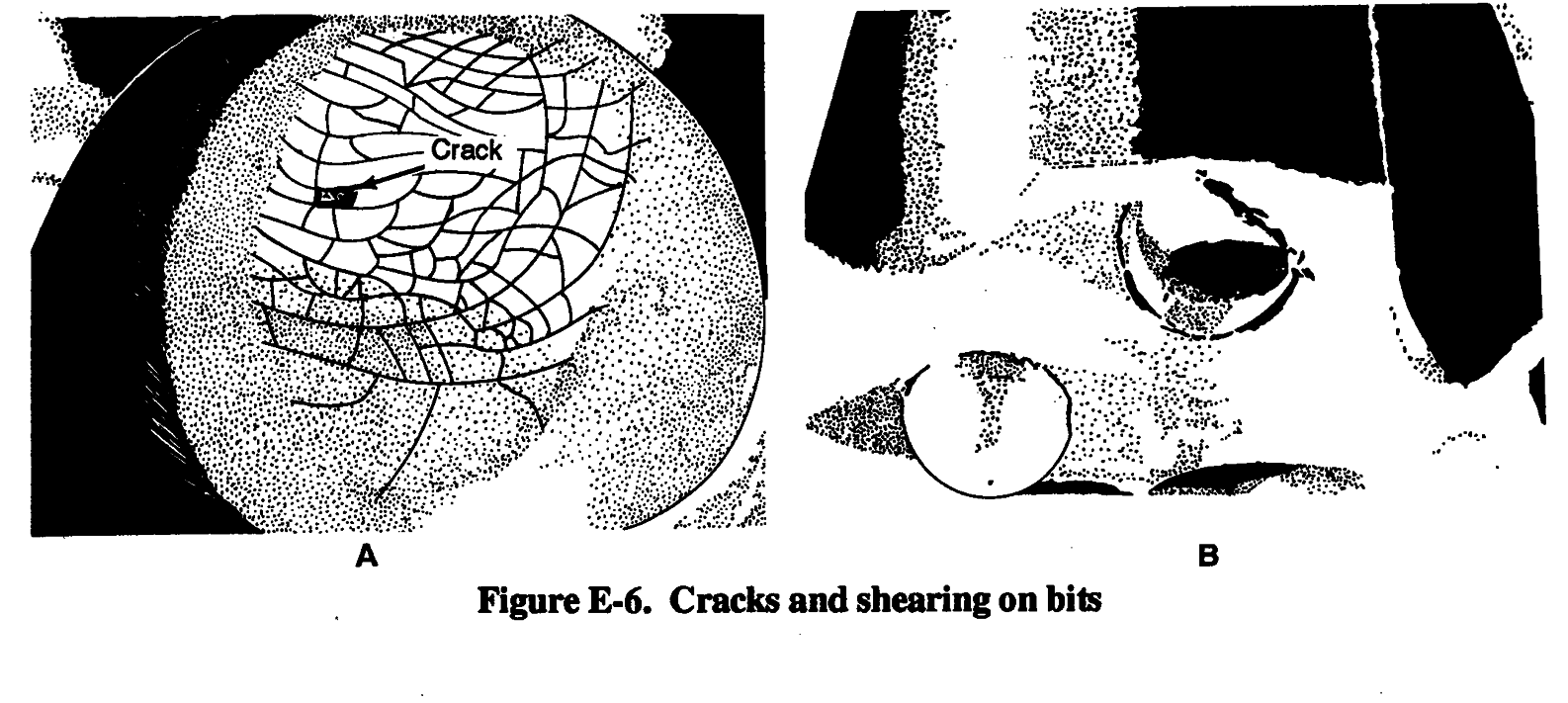
Progressive heat checking in the developed flats indicates excessive RPM. Small cracks (Figure E-6, A) develop on the face of the flat and if not reconditioned, breakdown of the button continues until it finally splits. The button then shears off and the effectiveness of the bit is lost (Figure E-6, B). A good rule of thumb is to rotate at the lowest RPM that permit smooth operation.
E-3


FM 5-484/NAVFAC P-1065/AFMAN 32-1072
Another condition that can result in carbide shear is drilling through bent casing (Figure E-7, A). A bent casing will cause the carbides to be pinched as the drill string passes through it and the carbide breaks as a result. Also, when changing bits after starting a hole, do not put a larger bit into an existing smaller diameter hole. Always measure bit gauge and use the larger bit first to prevent pinching the gauge carbides (Figure E-7, B).
After many hours of drilling in
nonabrasive soft rock the carbide begins to
fatigue. A network of fine cracks appear
and small flecks of carbide break away
(Figure E-8). The buttons have a polished
effect with no flats, and there is minimum
abrasive wear on the bit body. If not
checked, this will lead to further
breakdown of the carbide, side loading, and
carbide shear. To prevent this type of
failure in soft formation drilling,
reconditioning must be scheduled at
intervals that do not exceed 10 percent of
the overall life expectancy of the bit.
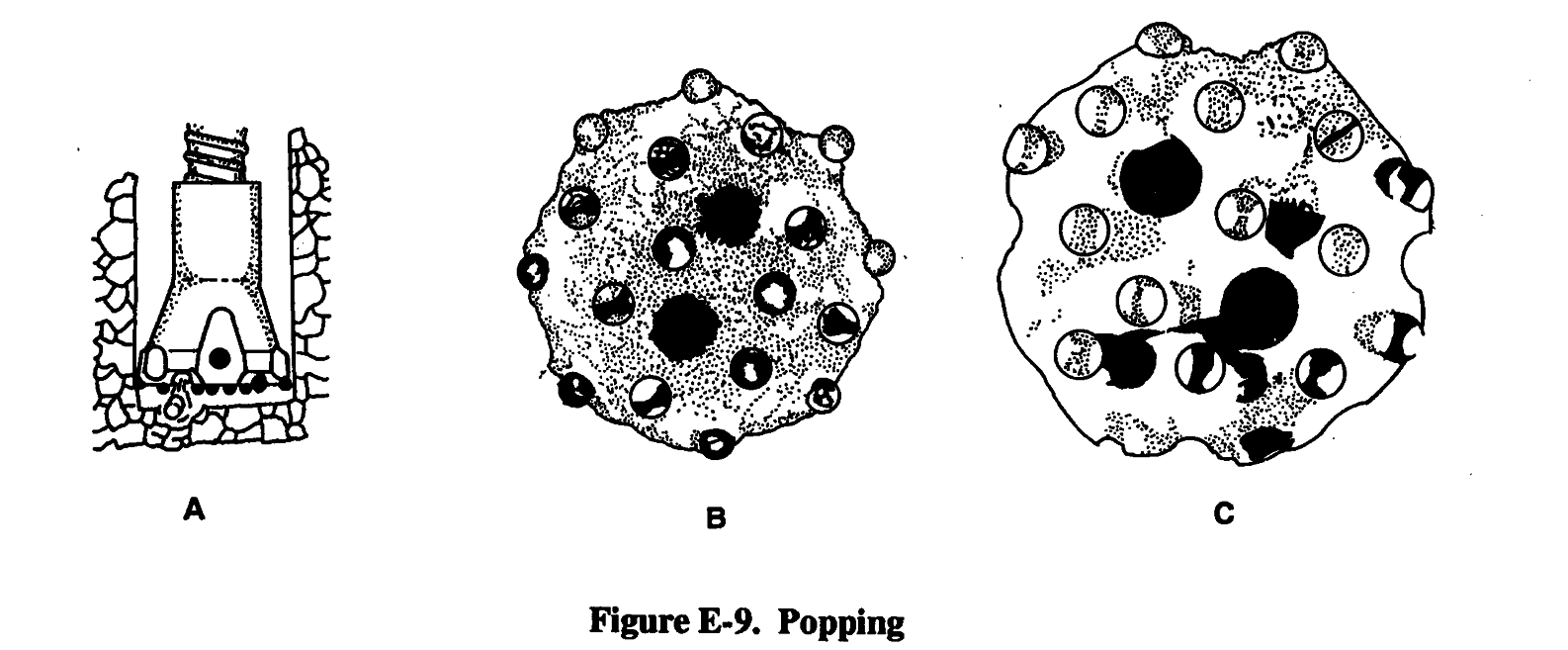
Popping of carbide inserts is a result of loose running. A carbide will pop clean from its socket
if the drill string is not properly fed up in the hole (Figure E-9, A). This is most common in
overburden drilling or in broken and unconsolidated formations. A large amount of energy is produced from the piston striking the shank in drifter drilling or the bit in down-hole drilling if the bit is not fed up to the rock. Instead of breaking the rock, this energy is retained in the bit and will
cause the carbides to pop (Figure E-9, B). When body metal around the carbide becomes too weak
—
reduces the life of the bit.
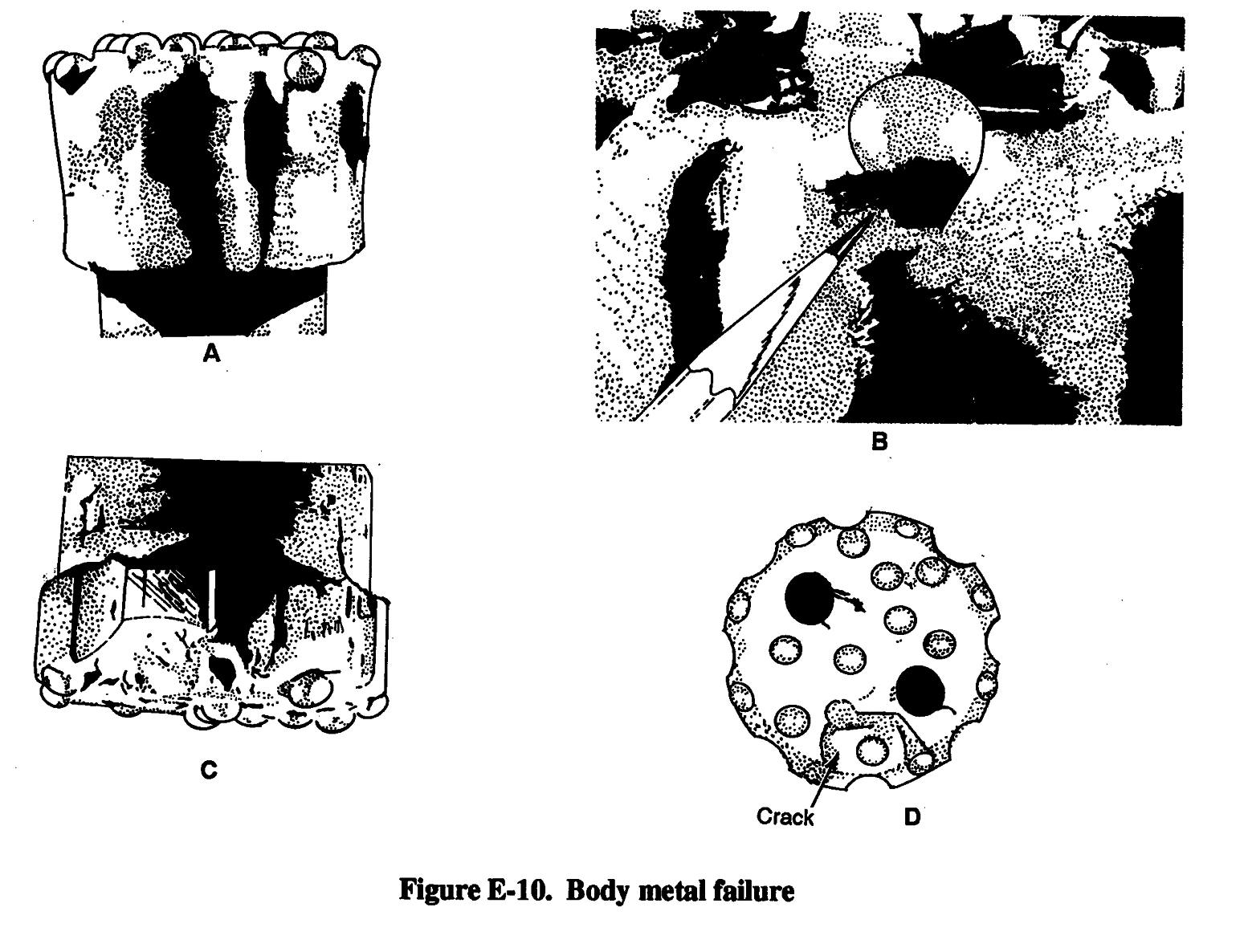
Body metal is another type of bit failure. Figure E-10, A shows a condition called body wash
(eroded body metal). Figure E-10, B shows the lip next to the button and the extent to which the
E-4
FM 5-484/NAVFAC P-1065/AFMAN 32-1072
button is protruding. The combination of a flat carbide and a large beam of exposed carbide generates side loading which fatigues the base in which the button rests. Figure E-10, C shows that the carbide and body have separated just below the rim of the socket while a fatigue crack has developed in the body metal. Cracks in the body (Figure E-10, D) can lead to entire pieces of the bit shearing off.
E-5

FM 5-484/NAVFAC P-1065/AFMAN 32-1072
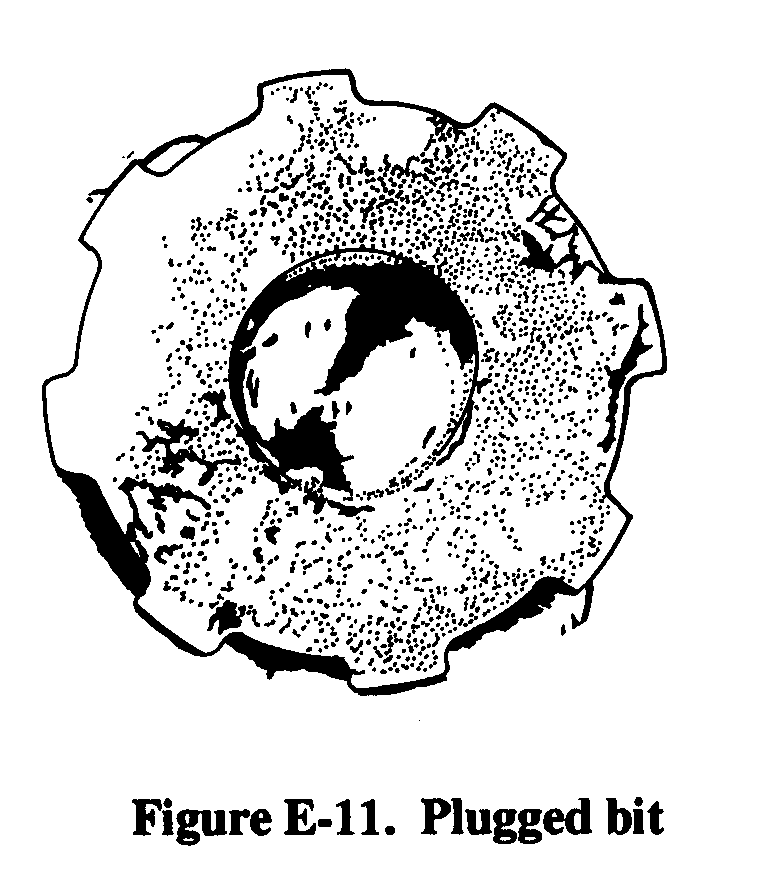
For optimum performance, introduce a bit to new rock regularity. If cuttings remain in the hole, the energy to break new rock is not transferred, putting undue stress on the bit, the drill, and the drill string. Each component will undergo more unnecessary stress and will fatigue faster and fail earlier. Figure E-11 shows an extreme example of what will happen if air is not continually fed down the hole. This bit has been plugged solid by the cuttings.
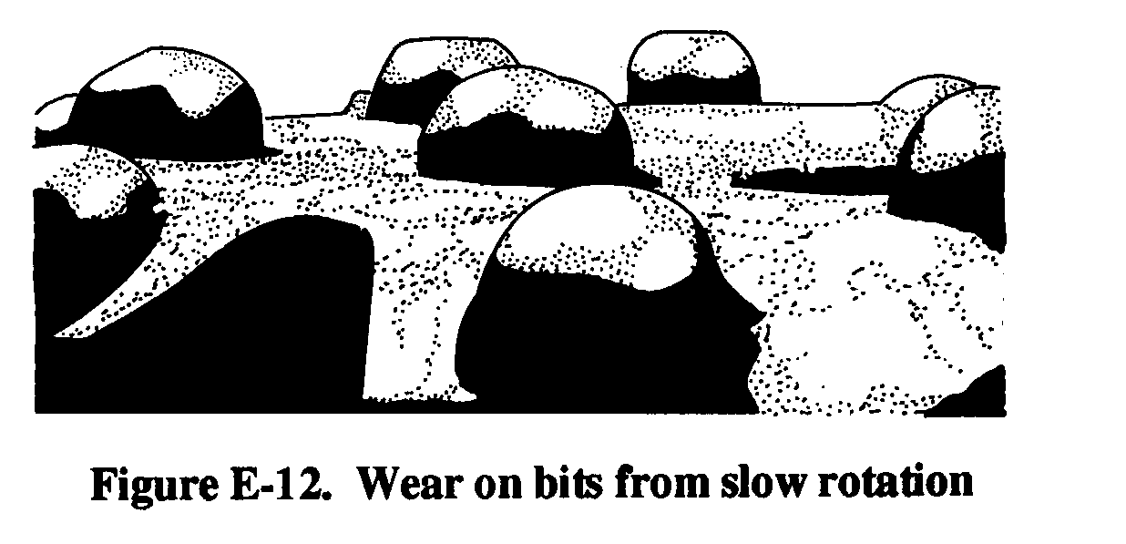
If rotation is too fast, flat spots, heat checks, and shearing will occur. If rotation is too slow, lopsided wear on the
carbides will occur. Figure E-12 shows a bit that has been
rotated too slowly. The button is barely out of the impression it made with the previous impact, when it is struck again.
Undue wear is caused on one side of the button, creating a
point on the carbide. When the point is sharp enough, it
chips, or portions of the button break away.
E-3. Reconditioning. The following lists some suggested equipment necessary for proper bit reconditioning:
A bit-grinding stand and a vitrified silicon carbide wheel that is 1 inch by 1 inch in diameter and rated at 25,000 RPM.
An I-R DIR DG121 grinder or its equivalent.
Safety glasses, hard hat, ear protection, and gloves
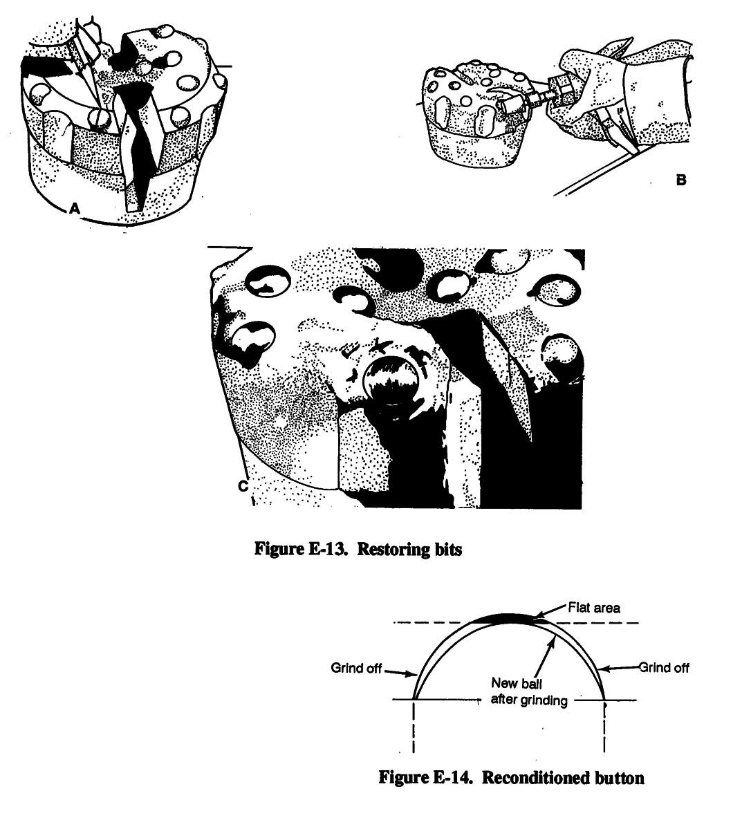
You must restore the original shape of the button when regrinding. To come close to this shape,
draw a pencil line down the center of the flat on the gauge button (Figure E- 13, A). Using the line
as a guide, grind the button on both sides, but leave the pencil line untouched (Figure E-13, B).
Leaving the pencil line ensures that the reground bit carbide will be concentric to the bit shank.
(When concentric, the carbides carry an equal share of the load.) Also, leaving the pencil line prevents you from grinding away too much carbide, thus extending bit life. Finally, blend the untouched line area (Figure E-13, C). When finished, the button should look almost new. Figure
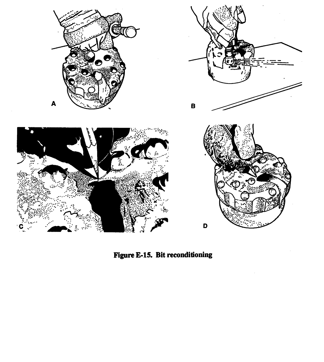
E-14 is a diagram of a reconditioned button. Although gauge buttons receive most of the wear,
check the blowholes (Figure E-15, C) and grind them back into shape (Figure E-15, D).
E-4. Rule of Thumb. In down-hole and drifter drilling, the most important factor contributing to poor performance and premature bit failure is operating the bit beyond the reconditioning point. A fixed guide outlining exact bit reconditioning intervals would be ideal. However, changing drilling E-6

FM 5-484/NAVFAC P-1065/AFMAN 32-1072
conditions make the establishment of such a guide unrealistic. Therefore, establishing such intervals will ultimately be determined on the job. Consider the following recommendations: In hard abrasive rock recondition at the first sign of a flat on the button bit. A flat width should never exceed 1/4 inch.
In soft or less hard abrasive formations, recondition before reaching 10 percent of the expected life of the bit. This prevents alligator-type failures and ensures proper bit life.
E-7
FM 5-484/NAVFAC P-1065/AFMAN 32-1072
E-8
FM 5-484/NAVFAC P-1065/AFMAN 32-1072
Glossary
ACE Assistant Chief of Engineers
aquifer Saturated rock or soil unit, such as gravel,
AF Air Force
sand, sandstone, limestone, and fractured
igneous and metamorphic rock, that has
AFI Air Force instruction
sufficient hydraulic conductivity to supply water
for a well or spring.
AFP Air Force pamphlet
aquitard A unit that retards or slows the passage
AFSC Air Force Specialty Code
of water.
air-foam-gel technique Adding foamer to a fluid
AR Army regulation
in the same proportions as clear water to get a
richer, more stable foam.
Ark Arkansas
air-lift method A pump-testing method that uses
ARTEP Army Training and Evaluation Program
an air-lift pump,
attapuigite Commercially processed clay used for
air-line method A procedure to measure the
drilling in brackish or salty water.
water level using an air line; the air line is
ATTN
copper tubing or galvanized pipe that is long
attention
enough to extend below the lowest water level
augered well A well that is bored using hand-or
being measured.
power-driven earth augers.
air rotary driling A well-drilling method that
AWWA American Water Works Association
uses compressed air as the circulating fluid.
alligatoring A network of fine cracks and small
carbide flecks on a bit that appear after hours of
backwashing Well-development method. See
drilling in nonabrasive soft rock.
also jetting method; gravity-outflow
method; pressure-pumping method;
alluvium Soils that are deposited by running
pump-surge method; surge-block method
water.
ball-down method Installing screen using a
alt attitude
special end fitting,
ant-mound-like openings. See qanat
bail-down placement A method of
simultaneously placing the gravel pack and
AO area of operations
installing the screen.
APOD aerial port of debarkation
Barafos A white, granular sodium tetraphosphate
APOE aerial port of embarkation
thinner and dispersant added to drilling fluid to
prevent mud from sticking to sand grains.
aquagel Commercial chemical agent added to
mud drilling fluid to prevent it from freezing.
barite Commercial chemical agent added to mud
See also barite; fibratex; gel-flake;
drilling fluid to prevent it from freezing. See
impermex; micatex; smentex
also aquagel; fibratex; gel-flake; impermex;
micatex; smentex
aquiclude Subsurface rock or soil unit, such as
clay, shale, and unfractured igneous and
barreling A wear pattern that causes the diameter
metamorphic rock, that does not transmit water
of the bit body to exceed the gauge diameter of
readily and cannot be used as a water-supply
the buttons.
source.
basalt An igneous rock that is a very productive
water bearer.
Glossary-1
FM 5-484/NAVFAC P-1065/AFMAN 32-1072
bentonite Commercially processed clay used for
cc cubic centimeter(s)
drilling; bentonite forms naturally from
decomposition of volcanic ash, consists of
centrifugal pump A variable displacement pump
aggregates of flat platelets, and contains sodium
in which water flows by the centrifugal force
montmorillonite, which is important in building
transmitted to the pump in designed channels of
viscosity.
a rotating impeller.
body metal A type of bit failure.
cfm cubic foot (feet) per minute
body wash Eroded body metal in bits.
cfs cubic foot (feet) per second
BOM bill of materials
circular-orifice meter A device used to measure
discharge rates.
boundary indicators Characteristics that are
indicative of local or regional groundwater flow
circular-orifice method A procedure to measure
systems.
discharge rates using a circular-orifice meter.
brass-jacket-type drive point Consists of a
closed-well method A compressed-air method
perforated pipe wrapped with wire mesh and
that involves using compressed air to close the
covered with a perforated brass sheet.
top of the well with a cap and by arranging the
equipment so air pressure can buiId up inside
brass-tube-type drive point Consists of a brass
the casing to force water out through the screen
tube slipped over perforated steel pipe for a
openings.
rugged construction.
cm cubic meter(s)
compressed-air methods Rapid, effective well-
cable jack A four-pronged receptacle located in
development methods. See also closed-well
the upper right comer of the panel on the
method; open-well method
electrical logging system.
CON DET A wetting agent added to drilling fluid
cable-tool method A very slow drilling method
to increase the dispersion action of
that can be used to penetrate rocky soil or
polyphosphates.
moderately hard sedimentary rock; the drill used
in this method does not require large amounts of
confined aquifer An aquifer that is completely
drilling fluid.
filled with water and is overlaid by a confining
bed.
CAL calibrate
confining bed Aquiclude that exists between
CAL ADJUST (calibration adjustment)
aquifers, water moves only within the aquifer.
Located in the lower right-hand comer of the
panel on the electrical logging system and used
consolidated deposit Rock that consists of
to zero the galvanometers when calibrating the
mineral particles of different sizes and shapes.
instrument.
continuous permafrost A zone where permafrost
carbide shear The most prevalent type of carbide
will be thick with no unfrozen ground. See also
breakage in bits
discontinuous permafrost; permafrost
casing ring and slip A device used to suspend the
continuous-slot drive point A screen with
casing at the ground surface and for pulling pipe
horizontal openings and one-piece welded
from the hole using jacks under each side of the
construction and contains no internal perforated
casing ring.
pipe to restrict the intake area.
catchment Formation whine impervious rock
CONUS continental United States
underlies a zone of fractured rock or alluvium
core barrel A double-tube sampler used to collect
that serves as a reservoir for infiltrated water; a
undisturbed soil samples in material that either
catchment can be a special type of aquifer.
contains gravel or is too hard for a thin-wall
cathodic protection. See sacrificial anode sample.
CB construction battalion
CPM critical-path method
Glossary-2
FM 5-484/NAVFAC P-1065/AFMAN 32-1072
crop irrigation Surface indicator that shows the
double-casing placement A method of placing
use of surface water or groundwater for
gravel using a temporary outer casing.
agriculture.
drainage basin An area drained by a stream or
CSS combat service support
river. See also hydrographic basin (local
CUR (current) A red plug receptacle used to
drainage basin); major river basin; regional
connect the surface-current ground wire to the
river basin
instrument.
drawdown Measure of how much the water level
current switch The ON-OFF switch located
near the well is lowered when the well is
directly below the function switch; the current
pumped.
switch is a momentary spring-return toggle
draw works Main drill-head hoists that are
switch.
mechanically or hydraulically driven wire-line
winches,
d depth
drilling blind A condition that exists when a
driller continues to drill when fluid circulation is
DA Departmnt of the Army
lost,
Darcy’s Law Principle that describes the flow of
drive clamp Uused in driving easing or pipe and is
groundwater.
attached to the square of the drill stem.
DC direct current
drive head Device that is placed on the pipe to
protect the threads the the driving blows of the
Denisen sampler, See core barrel
drive clamps; a drive head is put on by
DD Department of Defense
unscrewing the bit, slipping the drive head over
the drilling stem, and making up the joint again.
DHD down-hole drilling
drive monkey A weight that slides over the pipe
discharge Water that moves from one area into
and is used in the falling-weight method of
another.
driving a well.
discontinuous permafrost A zone where
driven method Installing casing as with the
permafrost will be thin and maybe absent on
borehole, the cable-tool, or driven-point well
the south slopes of hills, in valley bottoms
method.
containing permeable alluvial material, and
under surfaces that have been cleared of
drive point Perforated pipe with a steel point at
vegetation. See also continuous permafrost;
the lower end to breakthrough pebbles or thin,
permafrost
hard layers.
dispersion treatment Adding dispersing agents to
drive shoe Device attached to the lower end of the
drilling fluid, backwashing, jetting water, or
pipe to prevent the pipe from crumpling while
water standing in the well to counteract the
being driven; a drive shoe is threaded to fit the
tendency of mud to stick to sand grains.
pipe or casing.
dissolution potential The possibility of
dump-bailer method Placing grout in a casing
developing high secondary permeability in a
using a dump-bailer machine.
soluble rock because the rock dissolves through
contact with groundwater.
EAC echelons above corps
DMA Defense Mapping Agency
electric-line method A procedure to measure the
DOD Department of Defense
water level using an M-Scope. See also
dolomite A carbonate rock that dissolves when
M-Scope
carbon dioxide from the atmosphere and
electrode selector switch A five-position switch
groundwater mix to form carbonic acid.
located directly above the ohmmeter on the
electrical logging system.
Glossary-3
FM 5-484/NAVFAC P-1065/AFMAN 32-1072
elev elevation
foot piece A device at the end of an air pipe that
breaks the air into small streams so that the
elevator (casing) A device used to handle pipe;
bubbles formed will be as small as possible.
the elevator is clamped around the pipe directly
under the coupling. See also pin hook; sand
formation stabilizer Material placed on the
line
outside of the screen to help prevent
deterioration of the annular space; using
ENGR engineer
formation stabilizer is an alternative method to
evaporation Direct radiation from the sun that
using gravel-pack material.
causes liquid at the surface of a body of water to
fpm foot (feet) per minute
change from a liquid to a vapor.
ft foot (feet)
evaporite Sedimentary rock that is generally
capable of storing and transmitting groundwater
ft/min foot (feet) per minute
but teds to dissolve in the water
function switch A three-position selector switch
E-Z Mud A synthetic, inorganic polymer.
located directly beneath the galvanometers on the
electrical logging system.
F Fahrenheit
gal gallon(s)
fall-in Material that accumulates in the bottom of
the borehole after circulation stops,
galvanometers A zero-centered micrometer on the
electrical logging system.
falling weight Driving method that uses a steel
driving bar attached to a rope; the bar falls
gel-flake Commercial chemical agent added to
freely inside the pipe and strikes the base of the
mud drilling fluid to prevent it from freezing.
drive point.
See also