Section I. GRAVITY SYSTEMS
5-1. General.
5-2. Equipment.
a. In gravity systems, water flow is produced by
a. Pressure gauge/thermometer. For this type
the temperature difference between hot water in the
system, a combination pressure gauge and ther-
supply risers and cooler water in the return risers.
mometer is used. Water temperature in the system
The velocity and rate of flow through the system
is indicated on the thermometer scale and the
piping is low, so pipe sizes must be relatively large.
system pressure on a standard gauge dial.
Gravity systems may have either an open or a
b. Radiator valve. Each radiator has a valve for
closed expansion tank.
closing off circulation through the radiator. To
b. Distribution supply mains may be located in
prevent freezing of water in a radiator that is closed
the basement with up-feed to the radiators and
off, a weep hole is provided to allow sufficient
risers (as shown in figure 5-1), or the supply mains
water to circulate at all times. Unlike ordinary
may be located in the attic with overhead down-
steam or water pressure valves, there is no seal in
feed supply risers and return mains located in the
these valves. There is a barrel-like section in which
basement. The return connections are piped into a
a disk or gate makes a half turn to close the water
gravity return main which pitches downward to the
passage.
return opening in the boiler. Because there are
c. Radiator air vent. Each radiator has a com-
supply and return pipes throughout the building, all
pression air valve for venting air from the system
radiators are connected in parallel. The water
and radiator. Radiators are tapped at the top-feed
temperature is practically the same in all radiators,
and bottom return at opposite ends. Air is also
except for slight temperature drops in supply mains
vented from radiators through supply piping up-
between the boiler and the end of the circuit. Water
risers to the high point in the system, from which
temperatures at ends of circuits are lower than the
air is vented through a connection made to the ex-
rest of the circuit and are dependent on length of
pansion tank.
run and heating load. The rate of heat emission is
d. Expansion tanks. All heating systems require
also slightly lower per foot of radiation at the ends
an expansion tank to accommodate expansion and
of the circuit due to the slight drop in water
contraction of water which occurs as its tempera-
temperature.
ture changes. Excess water is stored in the expan-
sion tank until the water temperature decreases and
it is returned to the system. Gravity systems are
defined by the type of expansion tank installed:
open tanks or closed tanks.
(1) Open tank system. In open tank systems, the
expansion tank is freely vented to atmosphere.
Normally, these systems are limited to operating
temperatures of less than 180F.
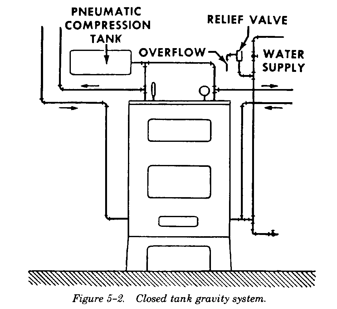
(2) Closed tank system. In closed tank systems
(figure 5-2), the expansion tank is airtight, sealed to
prevent free venting to atmosphere. As heated
water expands, the excess water moves into the
tank and compresses the entrapped air thereby in-
creasing the pressure on the system. When the
water temperature decreases, the water contracts,
air in the tank expands, the excess water returns to
the system, and the pressure drops. A closed ex-
pansion tank must be large enough to keep a res-
ervoir of compressed air above the water level to
cushion the excess water that enters. Thus the tank
must provide space for changes in both water and
air volume. A small tank with insufficient air can
5-1
TM 5-642
cause two undesirable conditions to occur. As the
occurs. It may be found necessary to add water to
temperature increases, the water expands and the
the system to enable venting of all radiators as the
system pressure may increase above the permissible
procedure progresses. A new system should be
level. This can cause the relief valve to open and
drained and refilled several times before starting the
waste water. As the temperature drops, the water
fire to remove grease, core sand, and other foreign
contracts and the pressure may drop below the
material. In the initial firing of a newly filled system,
permissible minimum. Air will not vent from the
it is advantageous to bring the system up to
system and additional air may be drawn in if the
temperatures considerably in excess of anticipated
high points of the system have automatic air vent
operating temperatures. This will tend to expel
valves.
entrained air from the system water and thoroughly
vent the system at start which will eliminate future
difficulties due to air pockets. After a new system
is in operation for a short period, open boiler
drains, since heavy core sand and similar materials
have a tendency to flow to this low part of the
system. When opening drains and feeding make-up
water to a hot water heating system in operation, be
careful that flow is not too fast. Otherwise,
excessive stress will be set up in the boiler structure
due to excessive temperature changes. After the
system has been fired approximately 10 days, open
air vents again and release air from radiators. Check
the system periodically for venting requirements.
5-4. Water level.
Probably the most important consideration in op-
erating a hot water system is maintaining the proper
water level in the expansion tank. Frequent
observation of the water level should be made. The
water level should be low enough in a cold system
to allow ample space for heated water to expand.
e. Boiler drain and cleanout openings. The low
point in the system has a boiler drain valve and the
5-5. Inspection and maintenance.
boiler is provided with rod-out openings so all
Operating difficulties of gravity systems are negli-
sediment, rust, and the like can be flushed out
gible, and corrective measures are seldom required.
readily.
Air which may accumulate in radiators should be
vented periodically to assure consistent heating
5-3. Startup.
system performance. If rapid fluctuation or
Close all vents, open all radiator valves, and open
pulsation of pressures should occur, check for
the water supply valve allowing water to flow until
system leaks, stoppages and relief valve operation.
the expansion tank is approximately half filled or
When a system is to be removed from service, drain
until water runs out of the overflow connection.
the system completely to remove accumulated
Beginning with the lowest radiators, open vent
sediment, rust, etc., and refill with clean water.
valves to remove air. Hold a small pail at each vent
and close the vent valve when free flow of water
Section II. FORCED CIRCULATION SYSTEMS
5-6. General.
differs from the gravity flow type only in that a
a. Forced circulation system piping and equip-
pump is installed at the termination of the
ment (figure 5-3) is similar to that of gravity flow
return piping near the boiler. Advantages of using
systems, except that pipe and equipment sizes are
a pump to produce the circulation are that much
generally smaller due to increased flow velocities.
smaller pipes are required and positive circulation
The general arrangement of the forced flow system
is assured throughout the system.
5-2

TM 5-642
thermometers are placed in the return or pro visions
are made for inserting immersion type test
thermometers near the pump. Circulation pump
rotation should be checked to make certain that
rotation is in the proper direction. Location of the
pump in the return line is suitable for small systems
where pump head is low, as in most residential
systems. Larger systems require the pump on the
supply side of the boiler, with the expansion tank
connected to the pump inlet.
b. Expansion tanks. Forced circulation hot water
systems almost always employ closed expansion
tanks. Since a closed expansion tank is sealed
against free venting to the atmosphere, the tank
may be above the highest radiator or heat trans-
mitter, or may be below the lowest one. The mini-
mum volume of a closed expansion tank is such that
expansion of water due to an increase in tem-
perature is cushioned against a reservoir of com-
pressed air above the water level in the tank. The
tank provides space not only for changes in water
volume, but also for variations in air volume within
the tank due to changes in air pressure. If the
b. There are some essential differences in circu-
closed expansion tank is below the radiators, the
lation in a forced circulation system as compared
tank is larger than if it is above them. The higher
with a gravity system. It is necessary to understand
the building the larger the air capacity should be
what takes place in order to remedy problems that
within the tank in excess of that required for
may be encountered in the field. The most
increase in water volume due to an increase in
important difference is that in the forced circulation
temperature. The closed expansion tank should be
system, the circulating force, neglecting gravity
located above the highest heat transfer surface in
effect, is produced locally by the pump. In the
tall buildings. A closed expansion tank located
gravity system, the circulating force is produced
above heat transfer surfaces of a hot water heating
uniformly throughout the system in the vertical runs
system should be connected by a direct pipe to the
of piping. A second difference is that the self-
flow main leaving the boiler in order to enable air to
regulating property of a gravity system is almost
migrate easily to the expansion tank. In a closed hot
lacking in the forced circulation system. Therefore,
water heating system, water tends to absorb air at
if pipe size and radiator connections in the forced
a rate which increases with an increase in pressure
circulation system are greatly restricted at some
and decreases with an increase in temperature.
points or improperly sized and balanced for uniform
Means should be provided to adjust and to observe
flow, the effect is likely to be serious.
the proportion of air within any closed expansion
tank. This includes provision of an air inlet valve, a
5-7. Equipment.
water gauge, and a relief valve. A source of
The principle equipment of a forced circulation
compressed air for renewing the air cushion is
system includes a boiler or heat exchanger, radia-
highly desirable, especially in large, high pressure
tors or fan-coil units, one or more circulating
hot water heating systems where it is inconvenient
pumps, an expansion tank, a relief valve, a hand or
and impractical to drain water in the system to
automatic fill valve to maintain set system pressure,
permit introduction of air.
and appropriate controls for pump operation and
c. Relief valves. All hot water heating systems
automatic firing equipment.
require proper provision for pressure relief. Equip-
a. Hot water pumps. Circulating or booster
ment can be subjected to excessive pressure by ex-
pumps are usually of the centrifugal type and are
pansion of confined water in the system if: connec-
installed in the pipe line with flanged fittings. In a
tions to expansion tanks are closed due to freezing
system that includes only one pump, each return
or other stoppage causes; the system*s expansion
line is connected to a common pump inlet header
tank becomes completely filled with water or; the
through a square-head cock to enable balancing of
air volume is inadequate to allow for necessary ex-
the system by equalizing return temperatures from
pansion. A conventional type hot water pressure
various circuits. In large installations immersion
relief valve which employs a spring-loaded dia-
5-3
TM 5-642
phragm to raise a valve seat when water pressure
standard hot water heating system equipment, and
exceeds 30 psig is installed in each system. This
the reducing valve setting should be kept as low as
valve is located in the cold water supply line be-
possible. The valve should be located at approxi-
tween the boiler and the reducing valve. The con-
mately the same level as the top of the boiler.
ventional reducing and relief valve installation does
not provide adequate protection for systems in
5-8. Piping systems.
which radiators are at boiler level as in a single
Forced circulation hot water heating systems gen-
story building without a basement where the boiler
erally use two-pipe systems. The two-pipe system
is installed at grade level in a utility room or similar
has two mains: the supply main which feeds water
location. Where radiators are at boiler level, instead
to the risers that serve the heating units, and the
of the conventional make-up water connection, an
return main which collects the water returned from
automatic water line regulator is installed in the
those units. The two mains run side by side; the
vertical riser between the main boiler take off and
supply main decreases and the return main increases
overhead expansion tank. The relief valve is located
in size where the branches connect. Since the
in the vertical riser at the water line of the
heating units of a two-pipe system are connected in
regulator.
parallel, a minimum pumping head is required.
d. Reducing valves. A reducing valve in the
Also, if throttle valves or restricting orifices are
make-up or cold water line to the boiler automati-
used in the risers, the flow through individual units
cally keeps the closed system supplied with water
can be adjusted easily over a wide range. The two-
at the predetermined safe system pressure. The
pipe system, however, requires more pipe and
valves are usually factory set at 12 psig pressure,
fittings than the one-pipe system. Two pipe systems
which is equivalent to a static head of 27.6 feet of
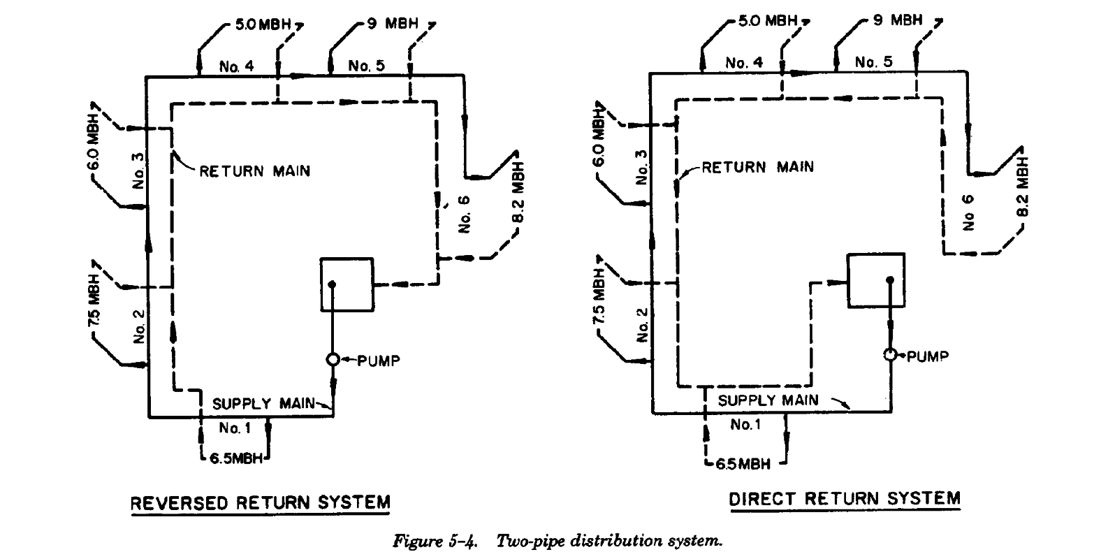
may be classified as either direct-return or reverse-
water, suitable for buildings up to three stories
return depending on the direction of the return
high. The valves can be reset for higher pressures if
(figure 5-4).
desired. Thirty (30) psig is the maximum for
a. Direct return systems (figure 5-4.2). The
tional circuits, the flow circuits are hydraulically
heating units of the two-pipe, direct return system
unbalanced. This condition may cause the first unit
are in parallel. Water taken from the main to feed
to have a greater flow than is required to develop
the first unit is returned first; that removed for the
its full capacity, while, in a large system, flow
second unit is returned second; and so forth
through the last unit may be so small that
throughout the heating units. Since this procedure
practically no heat is delivered. Restricting orifices
causes a progressively greater friction loss in addi-
or throttle valves are sometimes used to correct
5-4
TM 5-642
flow distribution and to balance the system after it
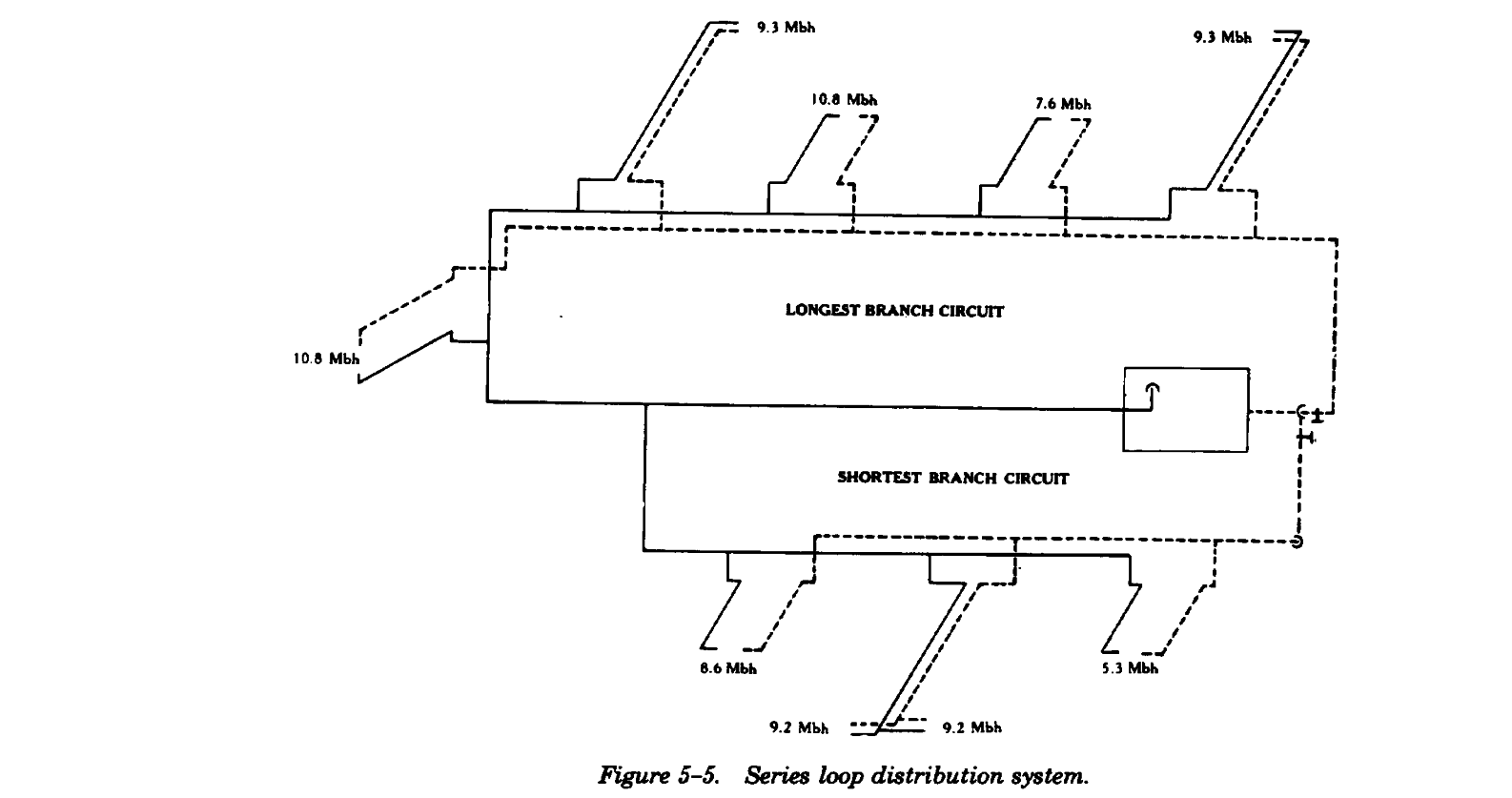
loop system may have one or more loops or
is placed in service.
circuits. All the heating units in a circuit are
b. Reversed return systems (figure 5-4.1). In the
installed in series and the same amount of water
two-pipe reversed-return system, water taken from
flows through each and through the connecting
the main to feed the first unit is returned last to the
main. For a given available head, the length of the
return main; the water supplied to the last unit is
circuit and the number and type of heating units de-
returned first. As a result, all unit circuits are
termine the water flow rate and temperature drop.
approximately equal in length, a condition
The water temperature decreases progressively as
conducive to system balance. The reversed return
the water flows through each successive heating
system may require more pipe than the direct
unit. Series systems are frequently used in connec-
return; however, its inherently better flow distri-
tion with baseboard radiation. Neither the flow nor
bution and natural balance without the aid of ad-
the temperature of the water supplied to individual
ditional valves or orifices, compensate for the addi-
heating units can be regulated in this system.
tional cost.
Delivery of heat, therefore, is usually controlled by
c. Series-loop systems (figure 5-5). A series-
air dampers in the baseboard radiation cabinets.
5-9. Inspection and maintenance.
capacity of the system and the size of the expansion
Generally, a good hot water heating system rarely
tank. Observe and record this characteristic when
presents operating difficulties if temperatures and
the system is in perfect operating condition. Any
pressures are kept within normal ranges. If rapid
later deviations from the established pressure may
fluctuation or pulsation pressures should occur,
indicate that the water level is low (if pressure
check for system leaks, stoppages, and relief valve
decreases) or that the system is stopped or plugged
operation. The indicated pressures of a closed
(if the pressure is above normal). When a system is
system may increase slightly with the increase of
to be removed from service, drain the system
water temperature. Each system has its own defi-
completely of accumulated sediment, rust, and the
nite increase characteristic, determined by the water
like, and refill with clean water.
5-5
TM 5-642
Section III. HOT WATER FAN-COIL UNITS
5-10.
General.
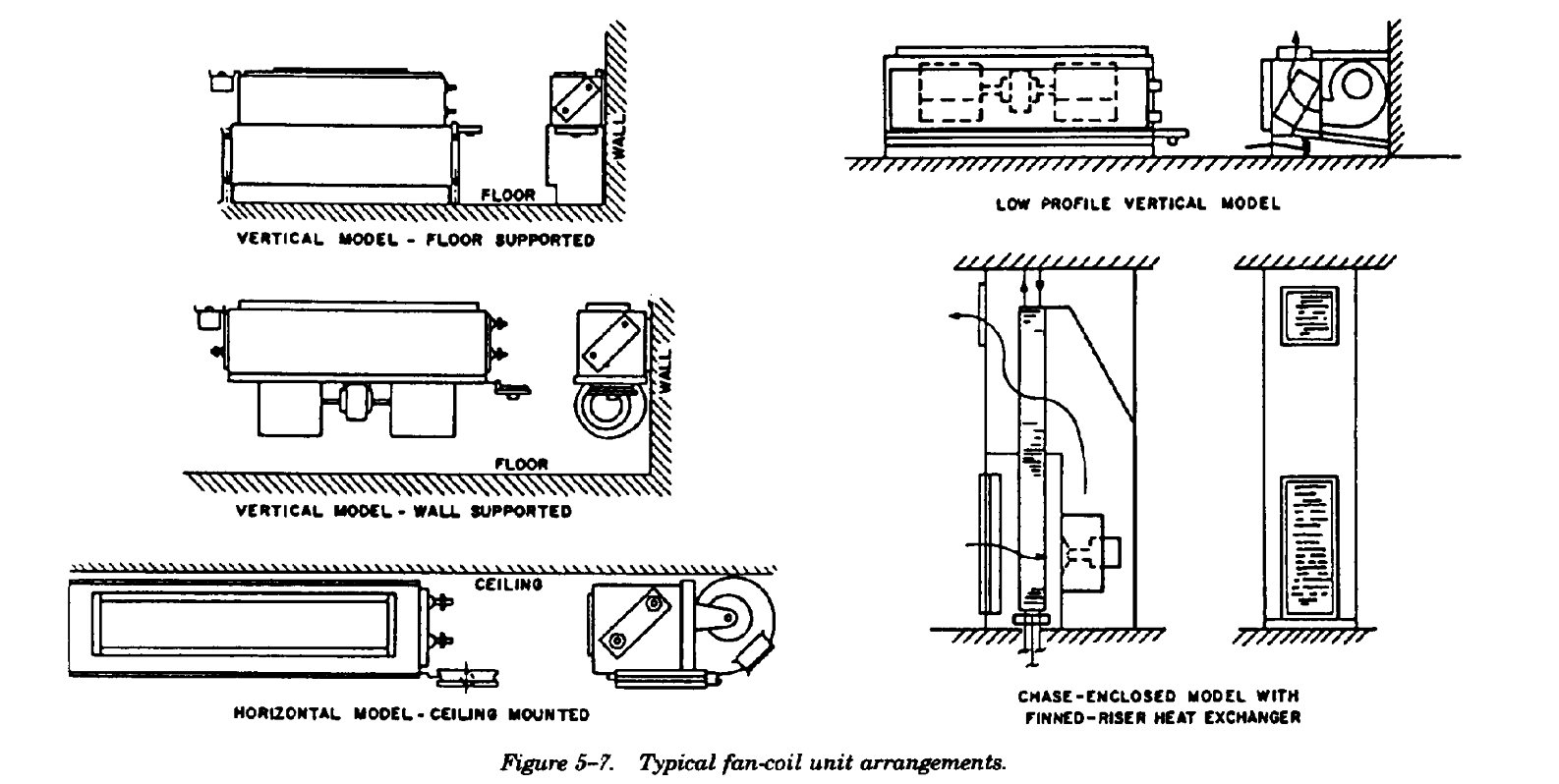
b. Room fan-coil units are available in a number
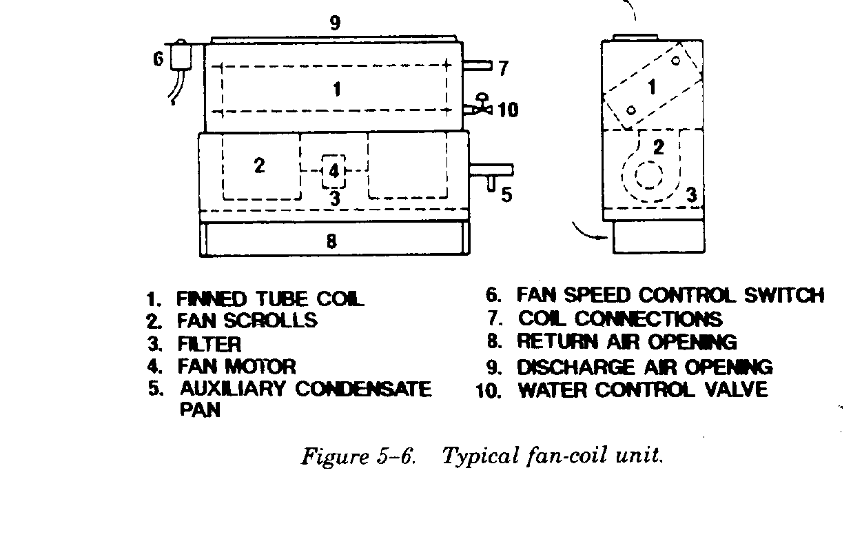
a. Basic elements of fan-coil units are a finned-
of physical configurations. Figure 5-7 show several
tube coil and a fan section (figure 5-6). The fan
arrangements of vertical wall mounted units and a
section recirculates air continuously from within the
horizontal ceiling mounted model. Low vertical
space through the coil which contains hot water.
units are available for use under windows with low
The unit may also contain chilled water or an
sills; however, in some cases the low silhouette is
electric resistance, steam, or hot water type of
achieved at a compromise of such features as filter
heating coil. A cleanable or replaceable low effi-
area, motor serviceability, and cabinet style.
ciency filter is located upstream of the fan. This
filter prevents the coil from becoming clogged with
dirt or lint entrained in the recirculated air. It also
protects the motor and fan, and reduces the level of
airborne contaminants within the conditioned space.
The unit is equipped with an insulated drain pan.
The fan and motor assembly is arranged for quick
removal to facilitate servicing. Ventilation air boxes
with a dampered opening for connection to
openings in the outside wall are optional.
5-6
TM 5-642
c. Floor-to-ceiling chase-enclosed units are
b. Water control valves should not be used
available in which the water and condensate drain
where aperture outdoor intakes are used, unless
risers are part of the factory furnished units. If the
there is a provision for freeze protection. Capacity
riser is located in the partition between two rooms,
control is achieved in certain configurations, by
both rooms can be served by the same unit. One
modulating a damper to bypass all or part of the air
style combines the water risers and coil into one
around the unit coil.
assembly by finning a portion of the water riser.
c. Fan speed control may be automatic or
Water flow is continuous through all units and air
manual. Automatic control is usually on-off with
bypass room temperature control is used. A
manual speeds selection. Some units are equipped
limitation of this style of unit is the size of the
with variable speed motors for modulated speed
finned riser; usually only 10 or 12 floors can be
control. Room thermostats are preferred where fan
stacked on a common riser. Another style of floor-
speed control is used. Return air thermostats will
to-ceiling unit overcomes this limitation by using a
not give a reliable index of room temperature when
separate coil which is sized independently of the
the fan is off.
risers.
d. If horizontal units are installed, air velocity
d. Horizontal overhead units may be fitted with
must be maintained to reach (throw) to the outside
ductwork on the discharge to supply several out-
wall area, and manual readjustment of fan speed
lets. A single unit may serve several rooms, e.g. in
may be undesirable.
an apartment house where individual room control
is not essential and a common air return is feasible.