easily; glasses no longer than 12 inches are
b. Keep gauge dials and glass covers clean and
preferable.
well lit to permit easy reading at any time.
c. Test and reset pressure gauges as required by
4-38.
Installing gauge glasses.
manufacturer*s instructions or when readings
a. Fuse cut ends since glasses are weakened by
appear abnormal.
broken surfaces.
d. Installation of suitable connections to each
b. Place glass connections in perfect alignment
boiler for inserting a test gauge is of great assist-
and free from strain on glasses. Jamming or twist-
ance. Install a tee connection on the gauge line so
ing glasses when tightening the stuffing box nuts
that a standard test gauge may be used to check the
causes breakage.
condition of an indicating gauge.
c. Gauge glasses are broken easily if scratched.
e. Never admit steam directly to the gauge. If
Exercise great care in storing.
steam is admitted to the gauge, the gauge should be
d. Gauge glasses should be protected from an
retested. Be sure the siphon is properly filled with
accidental blows. Provide rods or other means of
water at all times.
guarding the glass.
f.
Steam gauges on a battery of boilers should
e. Open and close all cocks slowly.
be graduated alike and should be of the same type.
f.
Wear goggles during this phase of installation.
Remove all broken pieces. Open valves slowly and
4-41.
Safety valves.
blow out any debris taking care to turn face away.
a. Never operate a boiler without one or more
Make sure new glass is of the proper length, that
safety valves of sufficient capacity as indicated by
the drain is open and connections are lined up.
the ASME Code. Keep those valves free and in
Insert glass, but do not set up too tight. Replace the
working order at all times.
guard if cocks must be opened and closed near the
b. Never place a stop valve between the boiler
position of the glass or cannot be operated from the
and a safety valve.
floor.
c. Test the safety valve periodically by lifting the
g. Open the top valve slightly and warm glass by
valve off of the seat by hand. This should not be
allowing a little steam to pass through so that heat
done unless the boiler pressure is from 80 to 85
is evenly distributed over the entire column. If
percent of the present popping point. Under no
water is admitted first, uneven heating may break
condition attempt to prevent safety valve leakage
the glass. When the water level appears steady,
by tightening the spring.
open the bottom valve wide and then open the top
d. When a safety valve does not pop at the re-
valve wide. Always test the water glass when
quired pressure, check carefully to determine the
replacement has been made. This should also be
cause. If the faulty valve condition cannot be cor-
done when the boiler is placed in service and when
rected, replace the valve.
difficulty is experienced with foaming or priming.
e. Set safety valves in accordance with ASME
Code requirements to pop at the proper pressure,
blow to reduced pressure, and close without chat-
4-33
TM 5-642
tering or simmer. All safety valves should be prop-
of leaky valves. Discharge ends of blowdowns
erly sealed after being set.
should be open for inspection at all times.
4-42.
Blow-down pipes.
4-43.
Dampers.
Maintain all valves, cocks, and lines carefully and
Inspect all dampers for looseness and other defects
inspect regularly for defects. Where leaks are dis-
before boiler is placed in service. Examine dampers
covered, make repairs as soon as practicable. Ex-
periodically and keep in good condition.
amine discharge end of blowoff pipes for indication
Section IX. TRAPS
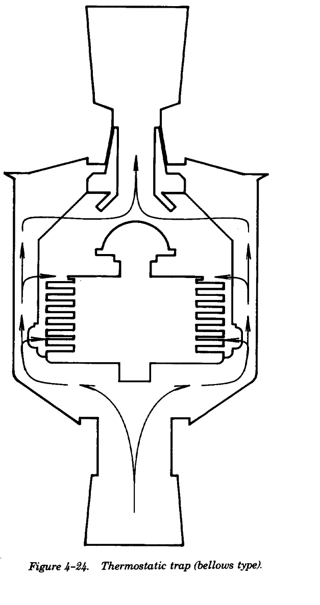
4-44.
General.
The basic purpose of a trap is to discharge conden-
sate, entrained air, and other gases from a steam
area, while preventing or minimizing loss of steam.
Various types of traps in use are: bucket,
thermostatic, combination float and thermostatic,
and thermodynamic traps. For steam heating sys-
tems, the thermostatic, or combination float and
thermostatic (F&T) are most commonly used.
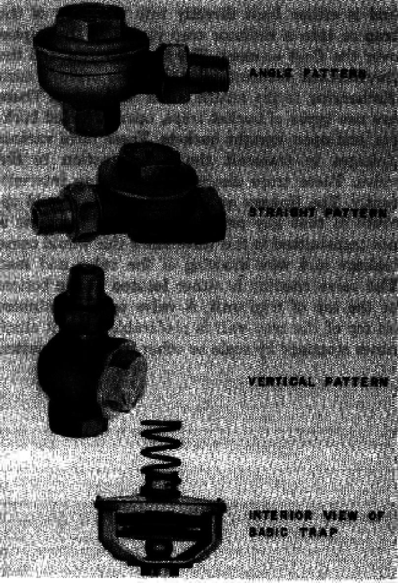
4-45.
Thermostatic traps.
Thermostatic traps are varied in design detail but
are classified as bellows or diaphragm type based
on the kind of expansion element used. (See figures
4-24 and 4-25).
4-34
TM 5-642
each radiator valve and remove the cap of each
thermostatic trap after the thermostatic unit has
cooled. Do not open thermostatic traps when they
are hot or when high vacuum is present in the
returns, since permanent distortion may occur to
the diaphragm or bellows. After the cap is removed
clean the trap interior, valve, and seat carefully with
a clean cloth. Do not clean seats, valve discs or
heads with abrasives, emery cloth, or files as
permanent scoring may result. It is important to
clean the trap during initial periods of new plant
operation as often as necessary and also im-
mediately following the shut-down of the heating
system for summer lay-up.
(5) When removing caps, use wrenches fur-
nished by the trap manufacturer to avoid damage to
heads and caps. Before replacing caps, carefully
wipe the threads clean and coat lightly with oil.
b. Maintenance.
(1) Clean the interior of thermostatic traps, in-
cluding diaphragm, valve seat and heads as required
by manufacturer*s instructions or as often as
required if water conditions cause excessive deposit
of solids, greases, or scale.
(2) A simple inspection check of the diaphragm
or bellows is accomplished by shaking the
diaphragm near the ear. Note by sound whether or
not the diaphragm contains liquid. Pull the valve
head to expand the thermostatic element slightly
and then compress to detect the sound of air or
liquid leaks. If the diaphragm or bellows leaks, it
must be replaced with a new element. Do not refill
Figure 4-25. Thermostatic traps (diaphragm type).
diaphragms, or patch and solder leaks, since
a. Installation.
charging and closing thermal elements requires a
(1) It is important to install traps so that the
factory process with exact procedures and
trap inlet is at or below the steam chamber and to
exceedingly close tolerances.
connect the discharge opening to the return piping
(3) If the valve head is damaged or scored,
so that condensate will return by gravity to the
remove it from the thermal element and replace it if
steam main. Thermostatic traps do not lift or siphon
possible; otherwise, install a new diaphragm or
condensate from a steam radiator. The top water
redress with special tools which are available from
line of a trap should be the top water line in the
the trap manufacturer. To regrind trap seats or
steam space served by the trap to ensure proper
discs, it is necessary to shim the diaphragm in re-
condensate drainage. Lower heat emission and
setting, with shims available from the manufacturer
efficiency of a heating unit may result due to partial
to compensate for metal removed from the valve
filling of the steam space by water which is backed
head or seat. Do not regrind or cut valve seats of
or held in the heating unit by a clogged or defective
the replaceable type, since the trap setting is
trap or a trap set too high.
disturbed by excessive removal of metal.
(2) The thermostatic trap is set so that the axis
c. Typical operating difficulties. Faulty traps
of the bellows or diaphragm is vertical to assure
will cause readily discernible operating difficulties.
that the thermostatic element is not partly immersed
Radiators will fail to heat due to air binding. This
in condensate.
may be caused by clogged traps or burst dia-
(3) The return pipe connections should be ar-
phragms. Bellows expand on release of their inter-
ranged so that expansion and contraction of the
nal vacuum and close the valve. Return lines
mains does not place strains on the trap.
become excessively hot due to cut valves and seats
(4) After the heating system piping, boilers and
which allow excessive steam leakage into return
other equipment are cleaned and in operation, shut
mains. Radiators will pound or have considerable
4-35
TM 5-642
water surging sounds when the trap lacks capacity,
thermostatic element of a radiator trap and is either
when trap is not properly set at the bottom of
built directly into the body of the trap or into a
eccentric radiator outlet bushings, or when the trap
radiator trap placed in the bypass over the float
is clogged. Defective traps should be returned to
element. The float element and the thermostatic
manufacturers for repair or replacement.
element have separate orifices, each discharging to
the return outlet of the trap. There are two types of
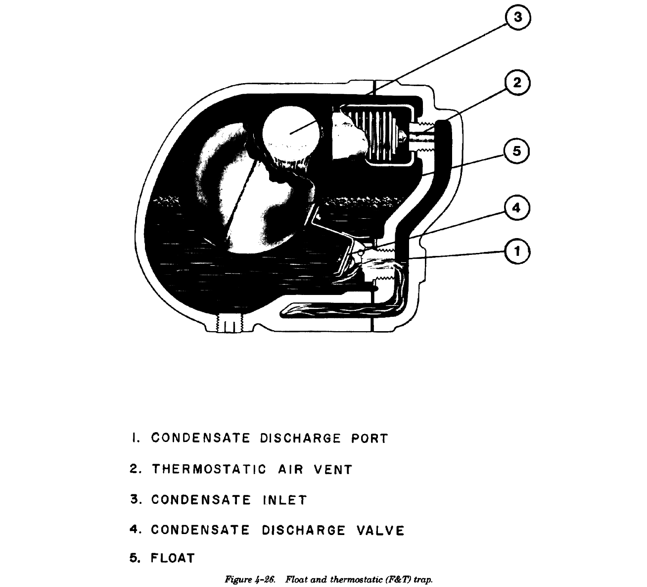
4-46.
Float and thermostatic traps and bucket
bucket traps, open inverted buckets, and open
traps.
upright buckets. These have various linkages to
These traps are installed on high capacity heating
transmit the bucket action to the valve. These traps
units such as unit heaters, blast coils, and hot water
discharge condensate intermittently. The linkage or
supply heaters. F&T traps are also used to drip
leverage system should operate so that any
ends of steam mains of closed vapor and vacuum
pulsating action of the float is not transmitted to the
heating systems. F&T traps consist primarily of two
valve since this would cause leakage and wire
elements: the float section which is intended to
drawing of the valve and seat. The valve opening is
handle the condensate, and the thermostatic
either located at the bottom or the top of trap unit.
element which consists of a diaphragm or bellows
A valve opening situated on top of the trap unit is
unit to pass air and gases. (See figure 426). The
preferable since it eliminates stoppage by scale or
thermostatic element is an exact duplication of the
other entrained matter.
4-36
TM 5-642
a. Installation. Float traps will not siphon or lift
other equipment which have readily accessible
condensate. The float trap must be installed so that
steam shutoff valves at the supply connection, need
the top water line of the trap is below the bottom of
not be provided with shutoff valves.
the equipment to be drained. The float trap must be
b. Operation and cleaning. After completion of
set level to eliminate binding of the leverage
replacement, remove any temporary blocks or ties
system. Trap connections at the end of mains
which are present to hold the float mechanism
should include a shut-off valve, vertical drop or dirt
during shipping and installation. If the trap is
pocket, strainer, and finally a drop into the return
equipped with a priming plug, open and fill the trap
main. The bottom of the dirt pocket should be fitted
with water. If a priming plug is not provided, open
with an easily removable cap for blowdown and
the valve to the steam line or heating unit supply
removal of dirt, scale, and grease. Float traps
valve and allow the trap to prime as condensate
installed on unit heaters or
accumulates in the body. This process may entail a
4-37
TM 5-642
short period of steam leakage. Open caps of
condensate could result in freezeup of extended
strainers and dirt pockets preceding traps at
surface coils used in ventilating work and of other
frequent intervals, or as indicated necessary, to
steam units exposed to ambient conditions. Keep a
assure removal of any accumulation of grease and
shop supply of serviced traps for quick replacement
scale. After traps have been in service on new in-
so that equipment need not be shut down during
stallations for a short period, remove covers, valve
repair operations.
head and seat, and wipe the internal mechanism
d. Typical operating difficulties.
thoroughly with a clean cloth to remove initial
(1) Steam leakage or blowby is the most
grease, scale, and accumulations of core sand. Peri-
common difficulty and is caused by float failures, a
odic opening of the trap drain plugs and blowdown
worn linkage or lever system, cut valves, or exces-
is effective in maintaining good trap service.
sive accumulations of dirt, rust, scale, and grease.
c. Maintenance. Check traps frequently to be
(2) Pounding and noise (water-hammer) in a
sure that they are operating properly. A correctly
heating unit or steam main indicates backup of
operating trap has a definite open and closed posi-
condensate due to inadequate trap capacity. Steam
tion, and the sound of condensate flow and shutoff
traps should be sized for 250 percent of the heating
can be detected easily by listening closely at the
unit capacity to permit excess condensate removal
discharge piping of the trap. Use a stethoscope to
during cold start-up. Noise is also caused by
check trap operation. Holding the stethoscope to
clogged traps or defective or jammed float mecha-
the trap body in the area of discharge provides a
nisms.
satisfactory method for checking trap performance.
(3) Air binding due to failure of the thermosta-
Repair or replace a trap immediately upon detection
tic element causes heating equipment failure and is
of blowing steam. This condition disrupts
usually detected by a relatively cool area preceeding
functioning of the heating system and further
the trap. Air binding creates an air pocket which
damage to the trap will result because of the cutting
prevents steam from filling the steam space of the
action of wet steam and condensate flowing
heating unit and the top of the trap. When this
through a scored or restricted opening. Blowing or
condition is present, backing off the thermostatic
leaking traps will also cause excessively hot returns.
element cover or opening the cleanout plug will
Inspect operating elements periodically; float
result in a rush of air followed by a rush of
failures or leakage of the ball or other closed type
condensate and steam. To correct this condition,
floats closes the valve and causes backup of
service the thermostat unit which may be either
condensate. Failure of an upright open bucket trap
clogged or closed by a ruptured thermostatic element.
element results in blowby but not in backup of
condensate. This failure is safe since backup of
Section X. AIR VENTS
4-47.
General.
ator in hot water systems. Vents at ends of steam
Air vents installed on radiators and ends of mains of
mains, unit heaters, and the like are usually of the
gravity heating systems consist of a combination
vertical straight shank type and are installed at the
thermostatic and float actuated valve stem and
top of a vertical pipe extension. The usual type vent
orifice, usually housed in a sealed casing. Some air
is sealed so that on-the-job repair is not practical.
vents include an adjustable orifice to increase or
Therefore, when placing a vent in initial operation,
decrease the vent rate, which provides for balancing
be careful not to force or inject excessive amounts
of the heating system.
of grease or scale into the vent.
4-48.
Installation and operation.
4-49.
Maintenance.
Vents, when installed on radiators, are located at
Remove vents from the system during the off-heat
the end opposite the steam connection. Radiators
season and allow to soak in a container of kerosene
for use with steam and hot water often have two
for approximately 24 hours to loosen rust and
vent tappings, one near the top and the other ap-
grease; then place in a vertical position, drain
proximately one third of the way down from the
thoroughly, and allow to dry. Air pressure is very
top. The lower opening is used for steam systems,
effective in blowing out vents following the kero-
since this is the location at which air will pocket
sene soaking process. When using air pressure for
between the top and bottom radiator section con-
removing dirt, use proper goggles for eye protec-
nections. The top opening is used to vent the radi-
tion.
4-38
TM 5-642
4-50.
Typical operating difficulties.
heating unit. If unsatisfactory vent performance
The most apparent failure occurs when a vent
cannot be corrected by cleaning procedures, replace
spouts water and steam caused by dirt on the valve
the vent. Manufacturers usually maintain a repair
or opening, by failure of the thermal element or by
service; consult the manufacturer for details of
a bent connection in a water pocket of the piping
factory servicing of vents when a quantity of
system. A clogged vent could result in air binding
defective units have accumulated and repair is
which would prevent steam from entering the
beyond the scope of local repair facilities.
Section XI. STEAM RADIATORS
4-51.
General.
flooring; legless radiators are firmly fixed to wall
There are two types of radiators: cast iron and ex-
brackets. Radiators are normally installed directly
tended surface units. Extended surface units are
under windows or at outside walls to offset
made up of relatively small tubes onto which metal
transmission and infiltration losses and provide
fins are formed. The tubes of extended surface units
comfortable room conditions. Reflectors can be
are either continuous or set in headers and the tube
provided behind radiators to get maximum heat
element is placed in a metal cabinet or enclosure
output, covering them should be avoided.
with circulating grilles at the top and bottom.
4-53.
Initial operation and cleaning.
4-52.
Installation.
After new radiators have been in service for a short
It is extremely important that radiators pitch toward
time, open and clean out thoroughly through the
the condensate discharge opening, particularly if the
return opening. Clean the outside of radiators
radiator is of the extended surface type. Radiator
frequently to maintain maximum heat output.
traps applied to extended surface radiators must be
in perfect operating condition; slight holdup of
4-54.
Typical operating difficulties.
condensate will greatly reduce the effectiveness of
Failure to heat due to stoppage or defective piping
this type of heating unit which has relatively small
causes radiator operating difficulty. Air binding will
available steam space. Traps of extended surface
also prevent radiators from heating properly. See
radiators are placed at an elbowed down
Section X on air vents. If radiators heat but no rise
connection, so that the trap is below the steam
occurs in room temperature, calculate the room
space to facilitate cleaning. Swing-through double-
heat loss and compare it with the quantity of
elbow joints should be used and ample length in
installed radiation. Reduce heat loss, if possible, by
supply and return branches to radiators should be
stopping cold air leaks through cracks, doors, and
provided so expansion and contraction of mains
windows of the area being heated. If radiator
will not cause breakage of radiator connections.
output is still insufficient, relocate radiation units or
Cast iron radiators require a firm setting on solid
install additional units.
Section XII. STEAM UNIT HEATERS
4-55.
General.
unit is increased. It is preferable to set the
Unit heaters consist primarily of an extended sur-
horizontal discharge to blow toward an outside wall
face steam coil and a propeller or blower fan which
at a large angle and to discharge all units in the
creates rapid flow of air through the heating coil.
same direction to form a continuous circuit of air
The basic types are horizontal and vertical
around exposed walls. Units placed in small rooms
discharge from ceiling suspension (figures 4-27 and
with low ceilings may be located on outside walls
4-28) and floor mounted horizontal blower units
with a recirculating duct to the floor to provide
(figure 4-29). Units are rated in BTU per hour or
even heating effects without undue draft conditions.
equivalent direct radiation (EDR) heat output and
Vertical discharge units are usually placed at room
cubic feet per minute air discharge capacity at given
ceiling or structural members and, since they