BUILDING A BIPLANE
EVERY one knows, of course, that the box-kite flies better than a plane surface, and many believe that the box or cellular type of aëroplane has a similar advantage over the monoplane. The enclosed end keeps the air from slipping off the edges of the plane, and makes for stability. There is all the difference in the world, or rather in the air, between an actual flight and the movement of a model aëroplane. The aviator, by flexing his planes, and adjusting his rudders fore and aft, may balance his craft to suit the air currents. In the model aëroplane, the adjustment must be made before starting once and for all. Several interesting principles are involved in the cellular or box form of aëroplanes which will well repay study (Plates 19-20).
In disturbed air, which is of course the usual condition of the atmosphere, the cellular model is likely to be deflected, and since the elevating plane or planes cannot be adjusted, it will soon fall off its course. Such models are easy to construct, and any one who has built a monoplane will have little difficulty with them. No attempt is made to flex the planes. The cellular type must be equipped with a lifting-plane forward, which may be easily adjusted to any angle, and held in position. It is indispensable that you have two propellers placed aft behind the main plane. The model may be made much more effective by adding a third stability-plane or rudder at the rear. It may be either vertical or horizontal and should be easily adjusted. The models illustrated, herewith, are very simple forms and clearly indicate the necessary frame work. It will be found that these models require considerable ballast, skilfully distributed.
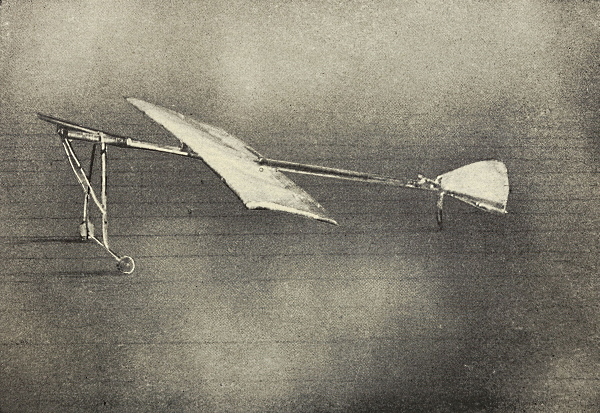
PLATE VI.
A Model with Both Good and Bad Features.
In building these cellular forms select some light lath for the frame rather than dowel sticks. It will be necessary to join many of these together at right angles, and the curved stick will be found difficult to work. For each box cut four sticks the desired width, and eight sticks the depth of your plane. The box should be almost exactly square so that all these shorter sticks should be the same length. Now build your box by nailing and glueing these sticks together, taking great pains to have it symmetrical. Should a single one of these sticks be too long or too short it will throw the entire frame out of plumb and make it next to impossible to get a straight flight.
In most of these models the front or rear stability-planes are made exactly like the larger frame only much smaller. When the frames are completed and thoroughly dry and smooth, stretch the cloth covering tightly over them by drawing it lengthwise, all the way around. By using a single piece of cloth it will be found easier to pull it together and hold it tight and smooth. It will be found a good plan to touch the outer edges of the frame you are covering with glue just before covering. When the glue dries the cloth will thus be held firmly in position. The cloth may be fastened to the outer edges by glueing or sewing.
A simple but effective plan for mounting the stability-planes is suggested by the models here illustrated. The frame of the motor-base may be made the width of the smaller frame and fastened between the two sticks. It should be left free so that it may be tilted up or down and fixed in any position. If the rear stability-plane is to serve as rudder it should of course be mounted vertically so that it may be turned to right or left. Be sure to make your frame sufficiently strong and rigid. A light frame which will vibrate when the motor turns or is shaken by the wind will be found very troublesome indeed.
The cylindrical forms of planes (Plate 21) carries the foregoing principles a step further. A surprising degree of stability is obtained by thus enclosing the air, and by throwing out several lateral stability-planes fore and aft. The models may be constructed of heavy wire, ordinary umbrella wire will answer the purpose, and may be readily bent. The planes in the accompanying model are merely suggestive. The broad planes placed forward, well above the diameter, promise well, but the rear wings appear unstable and small for the other surface. The forward or lifting-plane is again, much too narrow. The cylindrical form is equipped with a double propeller, one before and the other in the rear, both mounted on a bar, which forms the exact axis of the cylinder. This adjustment will give you a very pleasant surprise. The vibration and torque of the two propellers seem to equalize one another, and the thrust is much more steady than in the case of a single screw. The thrust is not only double, in this way, but the gain for stability is surprising. The model should be mounted on skids to assist it in rising, and to take up the force of the impact on landing.
The double propeller, mounted on the same shaft, may be used successfully in many models. A very simple monoplane form (Plate 22) may be equipped in this way. If two or more planes be mounted between the propellers, an astonishing soaring quality may be had. It is an excellent plan to fasten the planes to the frame at first by rubber bands, so that they may be pushed up or down readily, and adjusted and weighted to suit the conditions.
There is danger in this form, however, that the plane will turn completely over in its flight, although this will have little effect upon the thrust or direction. The model is exceedingly simple to make. The propellers should not be too large, not more than twice the diameter of the planes at most. The two propellers must, of course, be turned in opposite directions, to correct the twisting tendency.
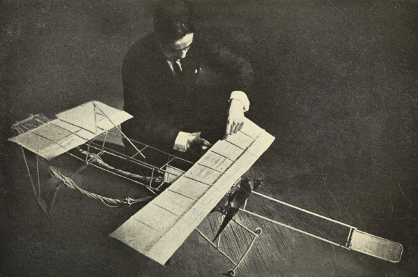
PLATE VII.
A Good Example of Careful Designing and Workmanship.
Should you construct a motor-base of this kind with propellers at either end it will be found interesting to experiment by attaching planes of different shapes and sizes. It requires very little surface to keep such a monoplane afloat. Instead of the circular and elliptical plane placed lengthwise, as in the accompanying model, try the effect of larger circles and broader ellipses, placing the latter sideways. This may be varied by using small rectangular planes with the corners rounded off. Sooner or later you will hit upon a shape of plane and a spacing which will give you good, steady flights of surprising length.
It has been suggested that a good motor-base be built with double propellers and the various forms of planes tested out upon it. Let us carry this idea further and, now that we have had some experience in building aëroplane models, construct a quadruple motor-base; that is a motor-base with four strands of rubber bands and four propellers, two forward and two aft. The four would of course have to be very nicely balanced. The two sets of propellers if carefully set up would tend to correct one another, as we have seen in the cylindrical and other double propellers thus giving a very steady flight. The increased speed of such a motor would carry any good model at a much higher rate of speed than any of the present forms.
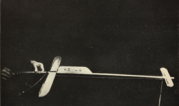
There is a very simple rule to be remembered in building all biplanes, regarding the spacing of the planes. The distance between the super-imposed planes should always be equal to the width of the planes themselves. A beautiful model (Plate 23) is here reproduced, to show how not to space your planes. In all other respects the model is excellent. The planes themselves are beautifully constructed and scientifically curved. It is interesting to note, in this case, that the front and rear sets of planes would be much too far apart were they flat surfaces, but being flexed as they are, their supporting power is greatly increased. By placing them so far apart, a longer and more powerful motor may be used. The rudders, both fore and aft, are adjustable, and appear very effective and shipshape.
The method of tuning up the planes in this model is especially to be recommended. From a post, placed at the center of the planes, wires are run to the corners which holds the frame perfectly taut. For the main frame, or backbone, a metal tube has been used which greatly adds to the appearance of the model. This aluminium tubing may be bought cheaply and will serve admirably for this purpose.
The most popular of all models, among amateur aëronauts in America, at least, is the Wright machine (Plates 24-25). The opinion is ventured that this is due more to the attractiveness of its lines and the pride we all take in its wonderful achievements, than to its actual flying ability as a model. The most perfect of these models will rarely fly more than a hundred feet. They will be found exceedingly difficult to weight and adjust so that they will maintain their course in a disturbed air current.
The planes of these models are usually made separate from the motor base. The shafts of the propellers, with the rubber motors and skids, are built up in a single piece. This plan has the advantage of making the planes adjustable so that they may move backward or forward as desired. The model leaves the ground from a base, much the same as the rail used by the large Wright machines. Some models are even started by the propulsion of a rubber band attached to the frame, which is pulled back and released, like the old-fashioned sling shot.