P The VST Dynamics panel is only available for regular audio channels (not for Group, ReWire or VST Instrument channels). There is, however, a plug-in simply named “Dynamics “which is available for all channel types. This plug-in is identical to VST Dynamics panel except that it does not have the “SoftClip” and “AutoLevel” processors. In addition, the Dynamics plug-in can be also be used as a Master Effect. See the separate document “The Included VST Effects” for additional information.
Each one of the “regular” audio channels (as opposed to ReWire, VST Instrument and Group channels) is equipped with an advanced Dynamics processor. Each VST Dynamics section combines five separate processors: AutoGate, Compress, AutoLevel, Limit and SoftClip, covering a variety of Dynamic Processing functions. The VST Dynamics window is divided into five sections, containing controls and meters for each processor. The audio input is tapped pre channel fader and pre EQ, and the internal signal flow is printed in the lower right part of the Dynamics panel.
The VST Dynamics processors are accessed on a separate panel for every audio channel, much like the EQ section. To open VST Dynamics from the VST Channel Mixer, proceed as follows:
• Click on the “DYN” button for an audio channel, either on the channel strip, or in the Inspector.
The Dynamics window opens, together with a duplicate of the channel strip, the Insert effect section and the effect sends section. As described on page 433, once you have opened a Dynamics window, you can open Dynamics panels for other channels without opening any new windows, by [Alt]-Clicking.
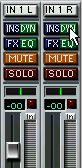 Clicking the “Dyn” button...
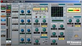 ...opens the VST Dynamics window for that channel. This is in fact the same window as the EQ window, only showing another “panel”. To view the EQ panel instead, click the EQ button.
About Dynamics on Stereo Channels
If you apply VST Dynamics to a stereo channel pair, the panel for the left channel will be used to make VST Dynamics settings for both channels.
 The AutoGate is activated.
You can activate as many processors as you want, but remember that not all processors are designed to work together. For example, “Limit” and “SoftClip” are both designed to ensure that the output never exceeds 0dB, but achieves this in different ways. To have both of them activated would be unnecessary.
• To turn off all activated VST Dynamics processors, click the lit On button in the lower right corner.
Clicking the button again activates the same configuration of processors.
P If you find that the audio playback signal is slightly delayed when you activate VST Dynamics, you should activate the “Plug-in Delay Compensation” option in the Audio System Setup dialog, as described on page 451.
VST Dynamics BypassYou can momentarily turn VST Dynamics on and off for a channel, to compare the sound with and without processing. There are two ways to do this:
• By using the Bypass button in the VST Dynamics section of the Channel Settings window.
• By right-clicking the “Dyn” button for a channel in the Mixer or in the Inspector.
 AutoGate section.
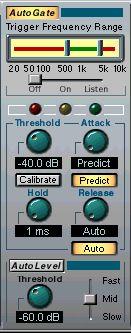
Gating, or noise gating, is a method of dynamic processing that silences audio signals below a certain set threshold level. As soon as the signal level exceeds the set threshold, the gate opens to let the signal through. AutoGate offers all the features of a standard noise gate, plus some very useful additional features, such as auto calibration of the threshold setting, a look-ahead predict function, and frequency selective triggering. Available parameters are as follows:
Parameter Threshold-60 - 0dB This setting determines the level where AutoGate is activated. Signal levels above the set threshold triggers the gate to open, but signal levels below the set threshold will close the gate.
0,1 -100 ms or This parameter sets the time it takes for the gate to open after being “Predict mode” triggered. If the Predict button is activated, it will ensure that the gate will already be open when a signal above the threshold level is played back. AutoGate manages this by “looking ahead” in the audio material, checking for signals loud enough to pass the gate.
0 - 1000 ms This determines how long the gate stays open after the signal drops below the threshold level.10 - 1000 ms or This parameter sets the amount of time it takes for the gate to close “Auto” (after the set hold time). If the “Auto” button is activated, AutoGate will find an optimal release setting, depending on the audio program material.
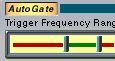
Trigger Frequency Range
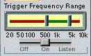
AutoGate has a feature that allows the gate to be triggered only by signals within a specified frequency range. This is a most useful feature because it lets you filter out parts of the signal that might otherwise trigger the gate in places you don’t want it to, thus allowing more control over the gate function. The Trigger Frequency Range function is controlled using the control in the upper part of the AutoGate panel, and the slider located below it. The basic operation of the Trigger Frequency Range function is as follows:
1. While playing back audio, drag the slider to the “Listen” position.You will now monitor the audio signal, and the gate will be bypassed.
2. While listening, drag the two handles in the Trigger Frequency window to set the frequency range you wish to use to trigger the gate.
You will hear the audio being filtered as you move the handles.
• Dragging the left handle to the right will progressively cut frequencies starting from the low end of the frequency spectrum.
• Dragging the right handle to the left will progressively cut frequencies starting from the high end of the frequency spectrum.
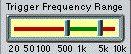 The frequency range between the two
 3. After setting the frequency range, drag the slider to the “On” position. AutoGate will now use the selected frequency range as the trigger input. 4. To disable the Trigger Frequency Range function, drag the slider to “Off”. AutoGate will now use the unfiltered audio signal as the trigger input.
Calibrate Function
This function, activated by using the Calibrate button located below the Threshold knob, is used to automatically set the threshold level. It is especially useful for material with consistent inherent background noise in the audio material, like tape hiss for example. This may most of the time be masked by the audio content, but becomes noticeable during silent passages. Use as follows:
1. Find a part of the audio material, preferably not too short, where only the background noise is heard.
If you can only find a short background noise section, try looping it.
2. Play it back, and click on the Calibrate button.
The button will blink for a few seconds, and then automatically set the threshold so that the noise will be silenced (gated) during passages where there is no other signal present.
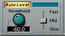
AutoLevel reduces signal level differences in audio material. It can be used to process recordings where the level unintentionally varies. It will boost low levels and attenuate high level audio signals. Only levels above the set threshold will be processed, so low level noise or rumble will not be boosted. If the input level is greater than 0dB, AutoLevel will react very fast, because it “looks ahead” in the audio material for strong signal levels and can attenuate levels before they occur, thus reducing the risk of signal clipping. AutoLevel has the following parameters:
Parameter Values
Threshold -90 to -10dB
Explanation
Only levels stronger than the set threshold will be processed.
This parameter sets the amount of time it takes for AutoLevel to adjust the gain. Set this according to whether the program level changes suddenly or over a length of time.
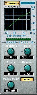
Compress reduces the dynamic range of the audio, so that softer sounds get louder or louder sounds get softer, or both. Compress functions like a standard compressor with separate controls for threshold, ratio, attack, release and make-up gain parameters. Compress features a separate display that graphically illustrates the compressor curve shaped according to the Threshold, Ratio and MakeUp Gain parameter settings. Compress also features a Gain Reduction meter that shows the amount of gain reduction in dB, and a program dependent Auto feature for the Release parameter. The available parameters have the following functionality:
Parameter Values ExplanationThreshold -60 - 0dB This setting determines the level where Compress “kicks in”. Signal levels above the set threshold are affected, but signal levels below are not processed.
Ratio 1:1 - 8:1 Ratio determines the amount of gain reduction applied to signals over the set threshold. A ratio of 3:1 means that for every three dB the input level increases, the output level will increase by only one dB.
Attack 0.1-100 ms This determines how fast Compress will respond to signals above the set threshold. If the attack time is long, it means that more of the early part of the signal (attack) will pass through unprocessed.
Release 10-1000ms or Sets the amount of time it takes for the gain to return to its original “Auto mode” level when the signal drops below the Threshold level. If the “Auto” button is activated, Compress will automatically find an optimal release setting, that varies depending on the audio program material.
MakeUp Gain 0 - 24dB This parameter is used to compensate for output gain loss, caused by compression.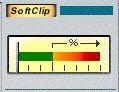
SoftClip is designed to ensure that the output level never exceeds 0dB, like a limiter. SoftClip, however, acts differently compared to a conventional limiter. When the signal level exceeds -6dB, SoftClip starts limiting (or clipping) the signal “softly”, at the same time generating harmonics which add a warm, tubelike characteristic to the audio material. SoftClip is simplicity itself to use as it has no control parameters. The meter indicates the input signal level, and thus the amount of “softclipping”. Levels in the green area (weaker than -6dB) are unaffected, while levels in the yellow-orange-red area indicate the degree of “softclipping”. The deep red meter area to the right indicates input levels higher than 0dB.
• Avoid feeding SoftClip with excessively high signal levels as audible distortion may occur, although the output level will never exceed 0dB.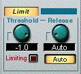
Limit is designed to ensure that the output level never exceeds a certain set output level, to avoid clipping in following devices. Conventional limiters usually require very accurate setting up of the attack and release parameters, to totally avoid the possibility of the output level going beyond the set threshold level. Limit adjusts and optimizes these parameters automatically, according to the audio material. However, should you want to, you can adjust the Release parameter manually. The available parameters are as follows:
Parameter Threshold Release Values Explanation-12 - 0dB This setting determines the maximum output level. Signal levels above the set threshold are affected, but signal levels below are left unaffected. When a signal is limited, the “Limiting” indicator is lit.
10-1000ms or This parameter sets the amount of time it takes for the gain to return to “Auto mode” its original level when the signal drops below the threshold level. If the “Auto” button is activated, Limit will automatically find an optimal release setting, that varies depending on the audio program material.