To be able to utilise the Studio Module to its full extent, you will need to establish two way communication with all your MIDI Devices. In other words, you will not only have to connect the MIDI Out(s) of your computer to the various devices, but you will also have to connect the MIDI Out of each Device to the MIDI In(s) of your computer.
If you have more than a couple of devices, you will need to get a MIDI Patchbay (sometimes called MIDI Switcher or MIDI Matrix) to set up this type of connection. You connect your computer and all (or some of) your gear to the Patchbay and then use the Patchbay to define what is connected to what.
Normally, you can send MIDI Program Change messages to a MIDI Patchbay, which will make it switch between different sets of routings. If you plan to get a MIDI Patchbay specifically for use with the Studio Module, make sure you get one that has this feature.
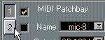
You can click on the small numbers to select which of the two MIDI Patchbays you want to edit. The Studio Module can handle two Patchbays “per Device”, for very complex setups. The two check boxes are used to turn them on/off. If you for example only have one, turn the other off. When you check/uncheck, the corresponding Patchbay also gets selected.
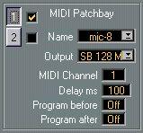
Although you can have "only" two Patchbays per Device, you can have many more Patchbays in your system. To save you some time when setting up each Device, you can pre-define some properties of each Patchbay you own. The settings that can be defined for a certain Patchbay are:
• Which MIDI Output on the computer the Patchbay is connected to.
• Which MIDI Channel it is on. If the Patchbay does not react to Program Change messages, this should be set to MAN, see below.
• How much Delay (in milliseconds) it needs to switch to a new routing. Some MIDI Patchbays take some time to switch in a new set of connections. You can use this value to specify that time. If you for example set this to 100 (=100 milliseconds, one tenth of a second), the Studio Module will always wait 100 milliseconds after "reprogramming" the MIDI Patchbay until it tries to access the Device that it just switched in.
• To create a new Patchbay definition, first make the Output, Channel and Delay settings, then click in the Name field and type in a new name – for example "A-880" if you have a Roland A-880. Now, when you pull down the Name pop-up, your "A-880" will appear, and if you select it, the Device which settings you are working on will get those Patchbay settings.
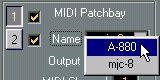 You can define up to 20 Patchbays like this.
• To Rename a Patchbay definition, double click on the existing name, type in a new one and press [Return].
If your MIDI Patchbay doesn't react to Program Change messages, you should set the MIDI Channel to "MAN" (Manual). If you do this, each time a new routing is needed, an alert box will inform you so that you can make the routings directly on the front panel of the Patchbay.
“Program After” is the Program number that will make your MIDI Patchbay switch to the "normal" connection, the one you use for recording into Cubase. Normally you will set all the Devices in the list to the same "Program After" number.
When you perform a Dump, things take place in the following order:
1. Program Before for Patchbay 1 is sent out.
2. Program Before for Patchbay 2 is sent out (if used).
3. The actual Data Dump takes place.
4. Program After for Patchbay 2 is sent out.
5. Program After for Patchbay 1 is sent out (if used).
If the Channel parameter for either Patchbay has been set to MAN (see above) the Program number will instead be used in a dialog box asking you to change the setting of the Patchbay before/after the dump.