Changing the Input Routing
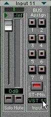
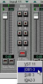
With the default routing of physical Inputs (see page 10), you only have access to the analog and digital inputs on the actual DS2416 card, not to any inputs on additional input/output units. If you have one or two input/output units installed, you may want to connect the inputs on these units to DS channels that normally take their input from VST. This is done using the Input pop-up menus in the Input Console window:
1. Open the Input Console window.
2. Locate a DS channel for which you want to change the input routing. Note that there are restrictions as to which inputs can be connected to which channels. This means that you cannot route any input to any DS channel - rather there is a fixed connection between the different inputs and the DS channels, as described below.
3. Select “Bus Assign” or “Aux Assign” mode for the channel’s Lower display, to show the Input pop-up menu.
It doesn’t matter which of these modes you select.

 4. Pull down the Input pop-up menu and select the desired input.
The table on the next page shows which inputs can be selected for each DS channel. Inputs on additional i/o units are labelled IOA1, IOA2, IOB1 or IOB2. “A/B” indicates whether the unit is connected as unit A or B, and “1/2” indicates a four-input unit (“1”) or an eight-input unit (“2”). “IOB2” therefore means “an eight-input unit connected as unit B”. The “SUB” inputs are described on page 41.
Channel Input Options
1 VST 1 IOB2-1
2 VST 2 IOB2-2
3 VST 3 IOB2-3
4 VST 4 IOB2-4
5 VST 5 IOB2-5
6 VST 6 IOB2-6
7 VST 7 IOB2-7
8 VST 8 IOB2-8
9 VST 9 IOB1-1 SUB 1 IOA2-1
10 VST 10 IOB1-2 SUB 2 IOA2-2
11 VST 11 IOB1-3 SUB 3 IOA2-3
12 VST 12 IOB1-4 SUB 4 IOA2-4
13 VST 13 IOA1-1 SUB 5 IOA2-5
14 VST 14 IOA1-2 SUB 6 IOA2-6
15 VST 15 IOA1-3 SUB 7 IOA2-7
16 VST 16 IOA1-4 SUB 8 IOA2-8
17 Analog In L IOA1-1 SUB 1 IOA2-1
18 Analog In R IOA1-2 SUB 2 IOA2-2
19 Digital In L IOA1-3 SUB 3 IOA2-3
20 Digital In R IOA1-4 SUB 4 IOA2-4
21 FX 1 Return L SUB 5 IOA2-5
22 FX 1 Return R SUB 6 IOA2-6
23 FX 2 Return L SUB 7 IOA2-7
24 FX 2 Return R SUB 8 IOA2-8


